HT46R23/HT46C23
The I2C Bus status register contains 5 bits. The HCF bit
is reset to ²0² when one data byte is being transferred. If
one data transfer is completed, this bit is set to ²1². The
HASS bit is set ²1² when the address is match, and the
I2C Bus interrupt request flag is set to ²1². If the interrupt
is enabled and the stack is not full, a subroutine call to
location 10H will occur. Writing data to the I2C Bus con-
trol register clears HAAS bit. If the address is not match,
this bit is reset to ²0². The HBB bit is set to respond the
I2C Bus is busy. It mean that a START signal is detected.
This bit is reset to ²0² when the I2C Bus is not busy. It
means that a STOP signal is detected and the I2C Bus is
free. The SRW bit defines the read/write command bit, if
the calling address is match. When HAAS is set to ²1²,
the device check SRW bit to determine whether the de-
vice is working in transmit or receive mode. When SRW
bit is set ²1², it means that the master wants to read data
from I2C Bus, the slave device must write data to I2C
Bus, so the slave device is working in transmit mode.
When SRW is reset to ²0², it means that the master
wants to write data to I2C Bus, the slave device must
read data from the bus, so the slave device is working in
receive mode. The RXAK bit is reset ²0² indicates an ac-
knowledges signal has been received. In the transmit
mode, the transmitter checks RXAK bit to know the re-
ceiver which wants to receive the next data byte, so the
transmitter continue to write data to the I2C Bus until the
RXAK bit is set to ²1² and the transmitter releases the
SDA line, so that the master can send the STOP signal
to release the bus.
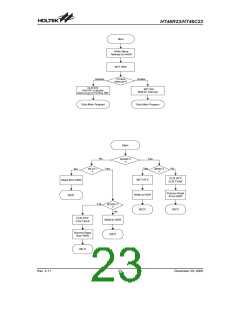
ister. At the beginning of the transfer of the I2C Bus, the
device must initial the bus, the following are the notes for
initialing the I2C Bus.
Note:
1. Write the I2C Bus address register (HADR) to define
its own slave address.
2. Set HEN bit of I2C Bus control register (HCR) bit 0 to
enable the I2C Bus.
Bit
Label
Function
No.
2~0
¾
Unused bit, read as ²0²
To enable or disable transmit ac-
knowledge (0=acknowledge; 1=don¢t
acknowledge)
3
TXAK
To define the transmit/receive mode
(0= receive mode; 1= transmit)
4
5~6
7
HTX
¾
Unused bit, read as ²0²
To enable or disable I2C Bus function
(0= disable; 1= enable)
HEN
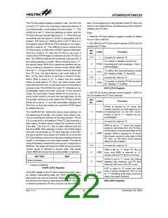
HCR (21H) Register
3. Set EHI bit of the interrupt control register 1 (INTC1)
bit 0 to enable the I2C Bus interrupt.
Bit
Label
Function
No.
RXAK is cleared to ²0² when the
master receives an 8-bit data and ac-
0
RXAK knowledgment at the 9th clock,
RXAK is set to ²1² means not ac-
knowledged.
The HADR bit7-bit1 define the device slave address. At
the beginning of transfer, the master must select a de-
vice by sending the address of the slave device. The bit
0 is unused and is not defined. If the I2C Bus receives a
start signal, all slave device notice the continuity of the
8-bit data. The front of 7 bits is slave address and the
first bit is MSB. If the address is match, the HAAS status
bit is set and generate an I2C Bus interrupt. In the ISR,
the slave device must check the HAAS bit to know the
I2C Bus interrupt comes from the slave address that has
match or completed one 8-bit data transfer. The last bit
of the 8-bit data is read/write command bit, it responds in
SRW bit. The slave will check the SRW bit to know if the
master wants to transmit or receive data. The device
check SRW bit to know it is as a transmitter or receiver.
1
¾
Unused bit, read as ²0²
SRW is set to ²1² when the master
wants to read data from the I2C Bus,
so the slave must transmit data to the
master. SRW is cleared to ²0² when
the master wants to write data to the
I2C Bus, so the slave must receive
data from the master.
2
SRW
3~4
5
¾
Unused bit, read as ²0²
HBB is set to ²1² when I2C Bus is
busy and HBB is cleared to ²0²
means that the I2C Bus is not busy.
HBB
Bit7~Bit1
Slave Address
Bit0
HAAS is set to ²1² when the calling
address has matched, and I2C Bus
interrupt will occur and HIF is set.
¾
6
7
HAAS
HCF
²¾² means undefined
HADR (20H) Register
HCF is clear to ²0² when one data
byte is being transferred, HCF is set
to ²1² indicating 8-bit data communi-
cation has been finished.
The HDR register is the I2C Bus input/output data regis-
ter. Before transmitting data, the HDR must write the
data which we want to transmit. Before receiving data,
the device must dummy read data from HDR. Transmit
or Receive data from I2C Bus must be via the HDR reg-
HSR (22H) Register
Rev. 2.11
22
December 29, 2008
图片预览")
 HOLTEK [ HOLTEK SEMICONDUCTOR INC ]