HT46RU25/HT46CU25
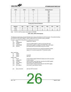
ACS2
ACS1
ACS0
Analog Channel
0
0
0
0
1
1
1
1
0
0
1
1
0
0
1
1
0
1
0
1
0
1
0
1
AN0
AN1
AN2
AN3
AN4
AN5
AN6
AN7
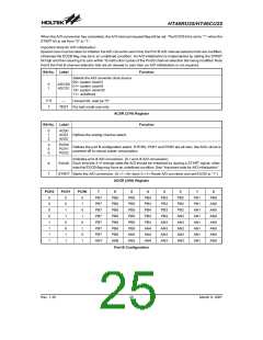
Analog Input Channel Selection
Register
ADRL
Bit7
Bit6
D2
Bit5
D1
Bit4
D0
Bit3
¾
Bit2
¾
Bit1
¾
Bit0
¾
D3
ADRH
D11
D10
D9
D8
D7
D6
D5
D4
Note: D0~D11 is A/D conversion result data bit LSB~MSB.
ADRL (24H), ADRH (25H) Register
The following programming example illustrates how to setup and implement an A/D conversion. The method of polling
the EOCB bit in the ADCR register is used to detect when the conversion cycle is complete.
Example: using EOCB Polling Method to detect end of conversion
clr
EADI
; disable ADC interrupt
mov
mov
mov
mov
a,00000001B
ACSR,a
; setup the ACSR register to select fSYS/8 as the A/D clock
; setup ADCR register to configure Port PB0~PB3 as A/D inputs
; and select AN0 to be connected to the A/D converter
a,00100000B
ADCR,a
:
:
; As the Port B channel bits have changed the following START
; signal (0-1-0) must be issued within 10 instruction cycles
:
Start_conversion:
clr
set
clr
START
START
START
; reset A/D
; start A/D
Polling_EOC:
sz
EOCB
; poll the ADCR register EOCB bit to detect end of A/D conversion
; continue polling
jmp
mov
mov
mov
mov
polling_EOC
a,ADRH
adrh_buffer,a
a,ADRL
; read conversion result high byte value from the ADRH register
; save result to user defined memory
; read conversion result low byte value from the ADRL register
; save result to user defined memory
adrl_buffer,a
:
:
jmp
start_conversion
; start next A/D conversion
Rev. 1.30
26
March 9, 2007

 HOLTEK [ HOLTEK SEMICONDUCTOR INC ]