HT46RU25/HT46CU25
I2C Bus Serial Interface
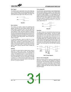
so the slave device is working in transmit mode. When
SRW is reset to ²0², it means that the master wants to
write data to the I2C Bus, the slave device must read
data from the bus, so the slave device is working in re-
ceive mode. The RXAK bit is reset to ²0² indicates that
an acknowledge signal has been received. In the trans-
mit mode, the transmitter checks the RXAK bit to deter-
mine the receiver which wants to receive the next data
byte, so the transmitter continues to write data to the I2C
Bus until the RXAK bit is set to ²1² and the transmitter
releases the SDA line, so that the master can send the
STOP signal to release the bus.
I2C Bus is implemented in the device. The I2C Bus is a
bidirectional two-wire lines. The data line and clock line
are implement in SDA pin and SCL pin. The SDA and
SCL are NMOS open drain output pin. They must con-
nect a pull-high resistor respectively.
Using the I2C Bus, the device has two ways to transfer
data. One is in slave transmit mode, the other is in slave
receive mode. There are four registers related to I2C
Bus; HADR([20H]), HCR([21H]), HSR([22H]),
HDR([23H]). The HADR register is the slave address
setting of the device, if the master sends the calling ad-
dress which match, it means that this device is selected.
The HCR is I2C Bus control register which defines the
device enable or disable the I2C Bus as a transmitter or
as a receiver. The HSR is I2C Bus status register, it re-
sponds with the I2C Bus status. The HDR is input/output
data register, data to transmit or receive must be via the
HDR register.
The HADR bit7-bit1 define the device slave address. At
the beginning of a transfer, the master must select a de-
vice by sending the address of the slave device. The bit
0 is unused and is not defined. If the I2C Bus receives a
start signal, all slave device notice the continuity of the
8-bit data. The front of 7 bits is slave address and the
first bit is MSB. If the address is matched, the HAAS sta-
tus bit is set and generates an I2C Bus interrupt. In the
ISR, the slave device must check the HAAS bit to deter-
mine whether the I2C Bus interrupt comes from the
slave address that has matched or completed one 8-bit
data transfer. The last bit of the 8-bit data is read/write
command bit, it responds in SRW bit. The slave will
check the SRW bit to determine whether the master
wants to transmit or receive data. The device checks the
SRW bit to know if it¢s a transmitter or a receiver.
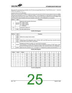
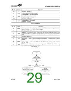
The I2C Bus control register contains three bits. The
HEN bit defines whether to enable or disable the I2C
Bus. If the data wants to transfer via I2C Bus, this bit
must be set. The HTX bit defines whether the I2C Bus is
in transmit or receive mode. If the device is as a trans-
mitter, this bit must be set to ²1². The TXAK defines the
transmit acknowledge signal, when the device received
8-bit data, the device sends this bit to I2C Bus at the 9th
clock. If the receiver wants to continue to receive the
next data, this bit must be reset to ²0² before receiving
data.
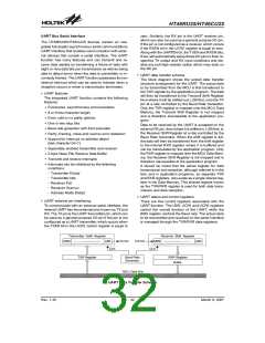
Bit7~Bit1
Bit0
Slave Address
¾
The I2C Bus status register contains 5 bits. The HCF bit
is reset to ²0² when one data byte is being transferred. If
one data transfer is completed, this bit is set to ²1². The
HAAS bit is set to ²1² when the address is matched, and
the I2C Bus interrupt request flag is set to ²1². If the inter-
rupt is enabled and the stack is not full, a subroutine call
to location 10H will occur. Writing data to the I2C Bus
control register clears HAAS bit. If the address is not
matched, this bit is reset to ²0². The HBB bit is set to re-
spond when the I2C Bus is busy. It means that a START
signal is detected. This bit is reset to ²0² when the I2C
Bus is not busy. It means that a STOP signal is detected
and the I2C Bus is free. The SRW bit defines the
read/write command bit, if the calling address is
matched. When HAAS is set to ²1², the device checks
the SRW bit to determine whether the device is working
in transmit or receive mode. When the SRW bit is set to
²1², it means that the master wants to read data from the
I2C Bus, the slave device must write data to the I2C Bus,
²¾² means undefined
HADR (20H) Register
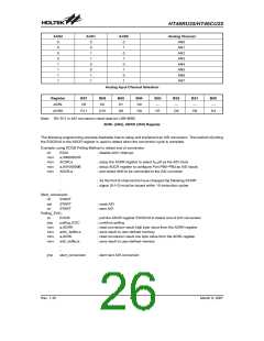
The HDR register is the I2C Bus input/output data regis-
ter. Before transmitting data, the HDR must write the
data which needs to be transmitted. Before receiving
data, the device must dummy read data from the HDR.
Transmitting or Receiving data from the I2C Bus must be
via the HDR register.
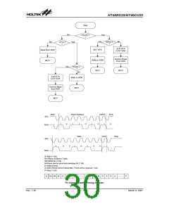
At the beginning of the transfer of the I2C Bus, the de-
vice must initialize the bus, the following are the notes
for initializing the I2C Bus:
Note: 1: Write the I2C Bus address register (HADR) to
define its own slave address.
2: Set HEN bit of the I2C Bus control register
(HCR) bit 0 to enable the I2C Bus.
3: Set EHI bit of the interrupt control register 1
(INTC1) bit 0 to enable the I2C Bus interrupt.
Rev. 1.30
28
March 9, 2007

 HOLTEK [ HOLTEK SEMICONDUCTOR INC ]