HT46RU25/HT46CU25
f
S Y S
8
-
s
t
a
g
e
P
r
e
s
c
a
l
e
r
f
I N T
D
a
t
a
B
u
s
8
-
1
M
U
X
T
2
M
1
R
e
l
o
a
d
8
-
B
i
t
T
i
m
e
r
/
E
v
e
n
t
T
2
M
0
T
2
P
S
C
2
~
T
2
P
S
C
0
C
o
u
n
t
e
r
P
r
e
l
o
a
d
R
e
g
i
s
t
e
r
T
M
R
2
(
1
/
1
~
1
/
1
2
8
)
T
2
E
8
-
B
i
t
T
i
m
e
r
/
E
v
e
n
t
P
u
l
s
e
W
i
d
t
h
O
v
e
r
f
l
o
w
T
2
M
1
M
e
a
s
u
r
e
m
e
n
t
C
o
u
n
t
e
r
(
T
M
R
2
)
T
2
M
0
t
o
I
n
t
e
r
r
u
p
t
M
o
d
e
C
o
n
t
r
o
l
T
2
O
N
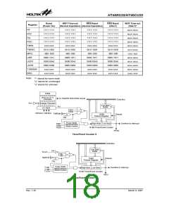
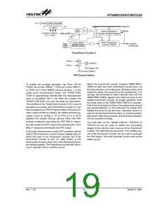
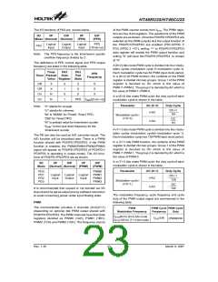
Timer/Event Counter 2
P
P
F
F
D
D
0
1
M
U
1
/
2
P
F
D
X
P
A
3
D
a
t
a
C
T
R
L
P
F
D
S
o
u
r
c
e
O
p
t
i
o
n
PFD Source Option
When the timer/event counter (reading TMR0/TMR1/
TMR2) is read, the clock is blocked to avoid errors, as
this may results in a counting error. Blocking of the clock
should be taken into account by the programmer. It is
strongly recommended to load a desired value into the
TMR0/TMR1/TMR2 register first, before turning on the
related timer/event counter, for proper operation since
the initial value of the TMR0/TMR1/TMR2 is unknown.
Due to the timer/event scheme, the programmer should
pay special attention on the instruction to enable then
disable the timer for the first time, whenever there is a
need to use the timer/event function, to avoid unpredict-
able result. After this procedure, the timer/event function
can be operated normally.
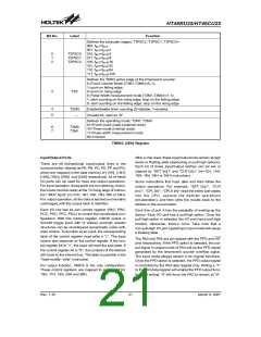
To enable the counting operation, the Timer ON bit
(T0ON; bit 4 of the TMR0C, T1ON; bit 4 of the TMR1C,
or T2ON; bit 4 of the TMR2C) should be set to 1. In the
pulse width measurement mode, the T0ON/T1ON/
T2ON is automatically cleared after the measurement
cycle is completed. But in the other two modes, the
T0ON/T1ON/T2ON can only be reset by instructions.
The overflow of the Timer/Event Counter 0/1/2 is one of
the wake-up sources, and Timer/Event Counter 0/1 can
also be applied to a PFD (Programmable Frequency Di-
vider) output at PA3 by options. No matter what the op-
eration mode is, writing a ²0² to ET0I, ET1I or ET2I
disables the related interrupt service. When the PFD
function is selected, executing the ²SET [PA].3² instruc-
tion will enable the PFD output and executing the ²CLR
[PA].3² instruction will disable the PFD output.
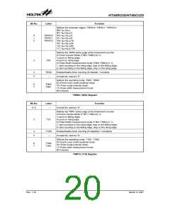
The bit0~bit2 of the TMR0C/TMR2C (T0PSC2~0/
T2PSC2~0) can be used to define the pre-scaling
stages of the internal clock sources of the timer/event
counter. The definitions are as shown. The overflow sig-
nal of the timer/event counter can be used to generate
the PFD signal. The timer prescaler is also used as the
PWM counter.
In the case of timer/event counter OFF condition, writing
data to the timer/event counter preload register also re-
loads that data to the timer/event counter. But if the
timer/event counter is turn on, data written to the
timer/event counter is kept only in the timer/event coun-
ter preload register. The timer/event counter still contin-
ues to operate until an overflow occurs.
Rev. 1.30
19
March 9, 2007

 HOLTEK [ HOLTEK SEMICONDUCTOR INC ]