HT45R37
·
Acknowledge Bit
Step 2
After the master has transmitted a calling address,
any slave device on the I2C bus, whose own internal
address matches the calling address, must generate
an acknowledge signal. This acknowledge signal will
inform the master that a slave device has accepted its
calling address. If no acknowledge signal is received
by the master then a STOP signal must be transmitted
by the master to end the communication. When the
HAAS bit is high, the addresses have matched and
the microcontroller slave device must check the SRW
bit to determine if it is to be a transmitter or a receiver.
If the SRW bit is high, the microcontroller slave device
should be setup to be a transmitter so the HTX bit in
the SIMCTL1 register should be set to ²1² if the SRW
bit is low then the microcontroller slave device should
be setup as a receiver and the HTX bit in the SIMCTL1
register should be set to ²0².
Set the SIMEN bit in the SIMCTL0 register to ²1² to en-
able the I2C bus.
Step 3
Set the ESIM and EMFI0 bits of the interrupt control
register to enable the I2C bus interrupt.
·
Start Signal
The START signal can only be generated by the mas-
ter device connected to the I2C bus and not by the
microcontroller, which is only a slave device. This
START signal will be detected by all devices con-
nected to the I2C bus. When detected, this indicates
that the I2C bus is busy and therefore the HBB bit will
be set. A START condition occurs when a high to low
transition on the SDA line takes place when the SCL
line remains high.
·
Data Byte
·
Slave Address
The transmitted data is 8-bits wide and is transmitted
after the slave device has acknowledged receipt of its
slave address. The order of serial bit transmission is
the MSB first and the LSB last. After receipt of 8-bits of
data, the receiver must transmit an acknowledge sig-
nal, level ²0², before it can receive the next data byte.
If the transmitter does not receive an acknowledge bit
signal from the receiver, then it will release the SDA
line and the master will send out a STOP signal to re-
lease control of the I2C bus. The corresponding data
will be stored in the SIMDR register. If setup as a
transmitter, the microcontroller slave device must first
write the data to be transmitted into the SIMDR regis-
ter. If setup as a receiver, the microcontroller slave de-
vice must read the transmitted data from the SIMDR
register.
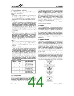
The transmission of a START signal by the master will
be detected by all devices on the I2C bus. To deter-
mine which slave device the master wishes to com-
municate with, the address of the slave device will be
sent out immediately following the START signal. All
slave devices, after receiving this 7-bit address data,
will compare it with their own 7-bit slave address. If the
address sent out by the master matches the internal
address of the microcontroller slave device, then an
internal I2C bus interrupt signal will be generated. The
next bit following the address, which is the 8th bit, de-
fines the read/write status and will be saved to the
SRW bit of the SIMCTL1 register. The device will then
transmit an acknowledge bit, which is a low level, as
the 9th bit. The microcontroller slave device will also
set the status flag HAAS when the addresses match.
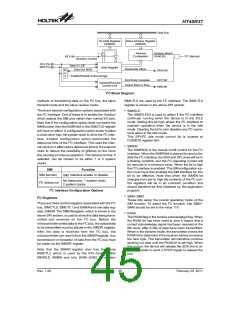
As an I2C bus interrupt can come from two sources,
when the program enters the interrupt subroutine, the
HAAS bit should be examined to see whether the in-
terrupt source has come from a matching slave ad-
dress or from the completion of a data byte transfer.
When a slave address is matched, the device must be
placed in either the transmit mode and then write data
to the SIMDR register, or in the receive mode where it
must implement a dummy read from the SIMDR regis-
ter to release the SCL line.
S
S
C
L
D
A
S
t
a
r
t
b
i
t
D
a
t
D
a
a
t
a
S
t
o
p
b
s
t
a
b
a
l
l
e
l
o
w
c
h
a
n
g
e
Data Timing Diagram
Receive Acknowledge Bit
·
·
When the receiver wishes to continue to receive the
next data byte, it must generate an acknowledge bit,
known as TXAK, on the 9th clock. The microcontroller
slave device, which is setup as a transmitter will check
the RXAK bit in the SIMCTL1 register to determine if it
is to send another data byte, if not then it will release
the SDA line and await the receipt of a STOP signal
from the master.
SRW Bit
The SRW bit in the SIMCTL1 register defines whether
the microcontroller slave device wishes to read data
from the I2C bus or write data to the I2C bus. The
microcontroller should examine this bit to determine if
it is to be a transmitter or a receiver. If the SRW bit is
set to ²1² then this indicates that the master wishes to
read data from the I2 C bus, therefore the
microcontroller slave device must be setup to send
data to the I2C bus as a transmitter. If the SRW bit is
²0² then this indicates that the master wishes to send
data to the I2C bus, therefore the microcontroller slave
device must be setup to read data from the I2C bus as
a receiver.
Rev. 1.20
48
February 25, 2011
图片预览")
 HOLTEK [ HOLTEK SEMICONDUCTOR INC ]