HT45R37
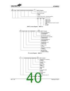
SPI Control Register - SIMCTL2
TRF flag will be set automatically, but must be cleared
using the application program. In the Slave Mode, when
the clock signal from the master has been received, any
data in the SIMDR register will be transmitted and any
data on the SDI pin will be shifted into the SIMDR regis-
ter. The master should output an SCS signal to enable
the slave device before a clock signal is provided and
slave data transfers should be enabled/disabled be-
fore/after an SCS signal is received.
The SIMCTL2 register is also used by the I2C interface
but has the name SIMAR.
·
TRF
The TRFbit is the Transmit/Receive Complete flag and
is set high automatically when an SPI data transmis-
sion is completed, but must be cleared by the applica-
tion program. It can be used to generate an interrupt.
·
WCOL
The SPI will continue to function even after a HALT in-
struction has been executed.
The WCOL bit is used to detect if a data collision has
occurred. If this bit is high it means that data has been
attempted to be written to the SIMDR register during a
data transfer operation. This writing operation will be
ignored if data is being transferred. The bit can be
cleared by the application program. Note that using
the WCOL bit can be disabled or enabled via configu-
ration option.
I2C Interface
The I2C interface is used to communicate with external
peripheral devices such as sensors, EEPROM memory
etc. Originally developed by Philips, it is a two line low
speed serial interface for synchronous serial data trans-
fer. The advantage of only two lines for communication,
relatively simple communication protocol and the ability
to accommodate multiple devices on the same bus has
made it an extremely popular interface type for many
applications.
·
CSEN
The CSENbit is used as an on/off control for the SCS
pin. If this bit is low then the SCS pin will be disabled
and placed into a floating condition. If the bit is high
the SCS pin will be enabled and used as a select pin.
Note that using the CSEN bit can be disabled or en-
abled via configuration option.
I2C Interface Operation
·
MLS
The I2C serial interface is a two line interface, a serial
data line, SDA, and serial clock line, SCL. As many de-
vices may be connected together on the same bus, their
outputs are both open drain types. For this reason it is
necessary that external pull-high resistors are con-
nected to these outputs. Note that no chip select line ex-
ists, as each device on the I2C bus is identified by a
unique address which will be transmitted and received
on the I2C bus.
This is the data shift select bit and is used to select
how the data is transferred, either MSB or LSB first.
Setting the bit high will select MSB first and low for
LSB first.
·
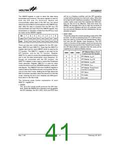
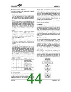
CKEG and CKPOL
These two bits are used to setup the way that the
clock signal outputs and inputs data on the SPI bus.
These two bits must be configured before data trans-
fer is executed otherwise an erroneous clock edge
may be generated. The CKPOL bit determines the
base condition of the clock line, if the bit is high then
the SCK line will be low when the clock is inactive.
When the CKPOL bit is low then the SCK line will be
high when the clock is inactive. The CKEG bit deter-
mines active clock edge type which depends upon the
condition of CKPOL.
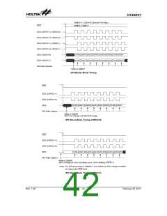
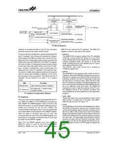
When two devices communicate with each other on the
bidirectional I2C bus, one is known as the master device
and one as the slave device. Both master and slave can
transmit and receive data, however, it is the master de-
vice that has overall control of the bus. For these de-
vices, which only operates in slave mode, there are two
S
T
A
R
T
s
i
g
n
a
l
CKPOL
CKEG
SCKClock Signal
f
r
o
m
M
a
s
t
e
r
High Base Level
0
0
Active Rising Edge
S
e
n
d
s
l
a
v
e
a
d
d
r
e
a
n
d
R
/
W
b
i
t
f
r
o
m
High Base Level
0
1
1
1
0
1
Active Falling Edge
A
c
k
n
o
w
l
e
d
g
e
Low Base Level
f
r
o
m
s
l
a
v
e
Active Falling Edge
Low Base Level
S
e
n
d
d
a
t
a
b
y
t
e
Active Rising Edge
f
r
o
m
M
a
s
t
e
r
SPI Communication
A
c
k
n
o
w
l
e
d
g
e
f
r
o
m
s
l
a
v
e
After the SPIinterface is enabled by setting the SIMEN
bit high, then in the Master Mode, when data is written to
the SIMDR register, transmission/reception will begin si-
multaneously. When the data transfer is complete, the
S
T
O
P
s
i
g
n
a
l
f
r
o
m
M
a
s
t
e
r
Rev. 1.20
44
February 25, 2011
图片预览")
 HOLTEK [ HOLTEK SEMICONDUCTOR INC ]