HT45R37
D
a
t
a
B
u
s
2
I
C
D
a
t
a
R
S
e
a
g
v
i
e
s
t
e
A
r
d
d
r
e
s
s
R
e
g
i
s
t
e
r
(
S
I
M
D
R
)
(
S
I
M
A
R
)
A
d
d
r
e
A
s
d
s
d
r
e
s
s
M
a
t
c
h
2
I
C
I
n
t
C
o
m
p
a
r
H
a
A
t
A
o
S
r
B
i
t
H
T
X
B
i
t
D
i
r
e
c
t
i
o
n
C
o
n
t
r
o
l
S
C
L
P
i
n
D
a
t
a
i
n
L
S
B
S
D
A
P
i
n
S
h
i
f
t
R
e
g
e
i
a
s
t
e
r
R
d
/
w
r
i
t
e
S
l
a
v
e
D
a
t
a
O
u
t
M
S
B
M
S
R
W
B
i
t
U
E
n
a
b
l
e
/
D
i
s
a
b
l
e
A
c
k
n
o
w
l
e
d
g
e
X
8
-
b
i
t
D
a
t
a
C
o
m
p
l e
t
t
e
H
C
F
B
i
T
r
a
n
s
m
i
t
/
R
e
c
e
i
v
e
D
e
t
e
c t
t
S
t
a
r
t
o
r
S
t
o
p
C
o
n
t
r
o
l
U
n
i
H
B
B
B
i
t
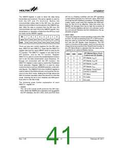
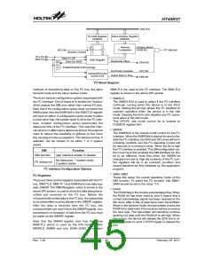
I2C Block Diagram
methods of transferring data on the I2C bus, the slave
transmit mode and the slave receive mode.
SIMCTL0 are used by the I2C interface. The SIMCTL0
register is shown in the above SPI section.
There are several configuration options associated with
the I2C interface. One of these is to enable the function
which selects the SIM pins rather than normal I/O pins.
Note that if the configuration option does not select the
SIMfunction then the SIMENbit in the SIMCTL0 register
will have no effect. A configuration option exists to allow
a clock other than the system clock to drive the I2C inter-
face. Another configuration option determines the
debounce time of the I2C interface. This uses the inter-
nal clock to in effect add a debounce time to the external
clock to reduce the possibility of glitches on the clock
line causing erroneous operation. The debounce time, if
selected, can be chosen to be either 1 or 2 system
clocks.
·
SIMIDLE
The SIMIDLEbit is used to select if the I2C interface
continues running when the device is in the IDLE
mode. Setting the bit high allows the I2C interface to
maintain operation when the device is in the Idle
mode. Clearing the bit to zero disables any I2C opera-
tions when in the Idle mode.
This SPI/I2C idle mode control bit is located at
CLKMOD register bit4.
·
SIMEN
The SIMEN bit is the overall on/off control for the I2C
interface. When the SIMENbit is cleared to zero to dis-
able the I2C interface, the SDA and SCLlines will be in
a floating condition and the I2C operating current will
be reduced to a minimum value. When the bit is high
the I2C interface is enabled. The SIMconfiguration op-
tion must have first enabled the SIMinterface for this
bit to be effective. Note that when the SIMEN bit
changes from low to high the contents of the I2C con-
trol registers will be in an unknown condition and
should therefore be first initialised by the application
program
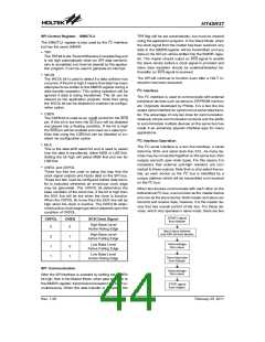
SIM
Function
SIM function
SIM Interface enable or disable
No debounce, 1 system clock;
2 system clocks
I2C debounce
I2C Interface Configuration Options
·
·
SIM0~SIM2
I2C Registers
These bits setup the overall operating mode of the
SIM function. To select the I2C function, bits SIM2~
SIM0 should be set to the value 110.
There are three control registers associated with the I2C
bus, SIMCTL0, SIMCTL1 and SIMARand one data reg-
ister, SIMDR. The SIMDRregister, which is shown in the
above SPI section, is used to store the data being trans-
mitted and received on the I2C bus. Before the
microcontrollerwrites data to the I2C bus, the actual data
to be transmitted must be placed in the SIMDR register.
After the data is received from the I2C bus, the
microcontroller can read it from the SIMDRregister. Any
transmission or reception of data from the I2C bus must
be made via the SIMDR register.
RXAK
The RXAKflag is the receive acknowledge flag. When
the RXAK bit has been reset to zero it means that a
correct acknowledge signal has been received at the
9th clock, after 8 bits of data have been transmitted.
When in the transmit mode, the transmitter checks the
RXAKbit to determine if the receiver wishes to receive
the next byte. The transmitter will therefore continue
sending out data until the RXAK bit is set high. When
this occurs, the device will release the SDA line to al-
low the master to send a STOP signal to release the
bus.
Note that the SIMAR register also has the name
SIMCTL2 which is used by the SPI function. Bits
SIMIDLE, SIMEN and bits SIM0~SIM2 in register
Rev. 1.20
45
February 25, 2011
图片预览")
 HOLTEK [ HOLTEK SEMICONDUCTOR INC ]