HT45R37
Interrupts
Interrupts are an important part of any microcontroller
system. When an external event or an internal function
such as a Timer/Event Counter or an A/D converter re-
quires microcontroller attention, their corresponding in-
terrupt will enforce a temporary suspension of the main
program allowing the microcontroller to direct attention
to their respective needs. The device contains several
external interrupt and internal interrupts functions. The
external interrupts are controlled by the action of the ex-
ternal INT0, INT1 and PINT pins, while the internal in-
terrupts are controlled by functions such as the
Timer/Event Counter overflows, the Time Base inter-
rupt, the RTC interrupt, the SPI/I2C interrupt, C/R to F
converter interrupt and the A/D converter interrupt etc.
from occurring. However, if other interrupt requests oc-
cur during this interval, although the interrupt will not be
immediately serviced, the request flag will still be re-
corded. If an interrupt requires immediate servicing
while the program is already in another interrupt service
routine, the EMI bit should be set after entering the rou-
tine, to allow interrupt nesting. If the stack is full, the in-
terrupt request will not be acknowledged, even if the
related interrupt is enabled, until the Stack Pointer is
decremented. If immediate service is desired, the stack
must be prevented from becoming full.
Interrupt Priority
Interrupts, occurring in the interval between the rising
edges of two consecutive T2 pulses, will be serviced on
the latter of the two T2 pulses, if the corresponding inter-
rupts are enabled. In case of simultaneous requests,
the following table shows the priority that is applied.
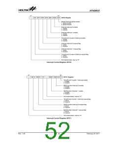
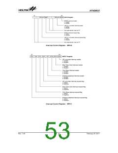
Interrupt Registers
Overall interrupt control, which means interrupt enabling
and request flag setting, is controlled by the INTC0,
INTC1, MFIC0, and MFIC1 registers, which are located
in the Data Memory. By controlling the appropriate en-
able bits in these registers each individual interrupt can
be enabled or disabled. Also when an interrupt occurs,
the corresponding request flag will be set by the
microcontroller. The global enable flag if cleared to zero
will disable all interrupts.
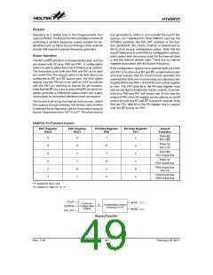
Interrupt Source
External Interrupt 0
Priority Vector
1
2
3
4
5
6
04H
08H
0CH
10H
14H
18H
External Interrupt 1
Timer/Event Counter 0 Overflow
Timer/Event Counter 1 Overflow
Multi Function 0 Interrupt
Multi Function 1 Interrupt
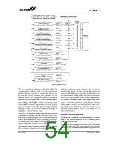
Interrupt Operation
A Timer/Event Counter overflow, Time Base, RTC over-
flow, SPI/I2C data transfer complete, C/R to F converter
interrupt, an end of A/D conversion or the external inter-
rupt line being triggered are some of the events which
will generate an interrupt request by setting their corre-
sponding request flag. When this happens and if their
appropriate interrupt enable bit is set, the Program
Counter, which stores the address of the next instruction
to be executed, will be transferred onto the stack. The
Program Counter will then be loaded with a new ad-
dress which will be the value of the corresponding inter-
rupt vector. The microcontroller will then fetch its next
instruction from this interrupt vector. The instruction at
this vector will usually be a JMP statement which will
jump to another section of program which is known as
the interrupt service routine. Here is located the code to
control the appropriate interrupt. The interrupt service
routine must be terminated with a RETI statement,
which retrieves the original Program Counter address
from the stack and allows the microcontroller to continue
with normal execution at the point where the interrupt
occurred.
The SPI/I2C interrupt, C/R to F converter interrupt share
the same vector which is Multi Function 0 Interrupt vec-
tor at location 14H. The A/D converter interrupt, Real
Time clock interrupt, Time Base interrupt and External
Peripheral interrupt share the same vector which is the
Multi Function 1 Interrupt vector at location 18H. Each
interrupt has its own interrupt flag but share the global
MF0F or MF1F Multi Function interrupt flag. The MF0F
and MF1F flags will be cleared by hardware once the
Multi-function interrupt is serviced, however the individ-
ual interrupts that have triggered the Multi-function inter-
rupt need to be cleared by the application program
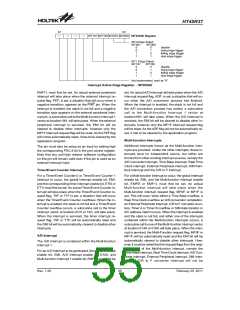
External Interrupt
For an external interrupt to occur, the global interrupt
enable bit, EMI, and external interrupt enable bits, EEI0
and EEI1, must first be set. Additionally the correct
interrupt edge type must be selected using the
INTEDGE register to enable the external interrupt
function and to choose the trigger edge type. An actual
external interrupt will take place when the external
interrupt request flag, EIF0 or EIF1, is set, a situation
that will occur when a transition, whose type is chosen
by the edge select bit, appears on the INT0 or INT1 pin.
The external interrupt pins are pin-shared with the I/O
pins PA6 and PA7 and can only be configured as
external interrupt pins if their corresponding external
interrupt enable bit in the INTC0 register has been set.
The various interrupt enable bits, together with their as-
sociated request flags, are shown in the accompanying
diagram with their order of priority.
Once an interrupt subroutine is serviced, all the other in-
terrupts will be blocked, as the EMI bit will be cleared au-
tomatically. This will prevent any further interrupt nesting
Rev. 1.20
51
February 25, 2011
图片预览")
 HOLTEK [ HOLTEK SEMICONDUCTOR INC ]