HT45R37
dresses match then this bit will be high, if there is no
match then the flag will be low.
S
t
a
r
t
·
HCF
W
r
i
t
e
S
l
a
v
e
The HCFflag is the data transfer flag. This flag will be
zero when data is being transferred. Upon completion
of an 8-bit data transfer the flag will go high and an in-
terrupt will be generated.
A
d
d
r
e
s
s
t
o
S
I
M
A
S
E
T
S
I
M
[
2
:
0
]
=
1
1
0
S
E
T
S
I
M
E
N
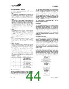
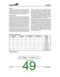
I2C Control Register - SIMAR
2
D
i
s
a
b
l
e
C
I
B
u
s
E
n
a
b
l
e
The SIMARregister is also used by the SPI interface but
has the name SIMCTL2.
I
n
t
e
r
r
u
p
t
=
?
S
E
T
E
S
I
C
L
R
E
S
I
M
P
o
l
l
S
I
M
F
t
o
d
e
c
i
d
S
e
e
t
E
M
F
The SIMARregister is the location where the 7-bit slave
address of the microcontroller is stored. Bits 1~7 of the
SIMAR register define the microcontroller slave ad-
dress. Bit 0 is not defined. When a master device, which
is connected to the I2C bus, sends out an address,
which matches the slave address in the SIMARregister,
the microcontroller slave device will be selected. Note
that the SIMAR register is the same register as
SIMCTL2 which is used by the SPI interface.
2
w
h
e
n
t
C
o
B
g
u
o
s
t
I
o
S
R
I
W
a
i
t
f
o
r
G
o
t
o
M
a
i
n
P
r
o
g
r
a
G
m
o
t
o
M
a
i
n
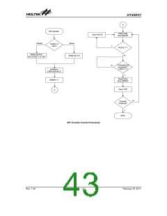
I2C Bus Initialisation Flow Chart
·
SRW
The SRW bit is the Slave Read/Write bit. This bit de-
termines whether the master device wishes to trans-
mit or receive data from the I2C bus. When the
transmitted address and slave address match, that is
when the HAAS bit is set high, the device will check
the SRW bit to determine whether it should be in
transmit mode or receive mode. If the SRW bit is high,
the master is requesting to read data from the bus, so
the device should be in transmit mode. When the
SRW bit is zero, the master will write data to the bus,
therefore the device should be in receive mode to
read this data.
I2C Bus Communication
Communication on the I2C bus requires four separate
steps, a START signal, a slave device address transmis-
sion, a data transmission and finally a STOP signal.
When a START signal is placed on the I2C bus, all de-
vices on the bus will receive this signal and be notified of
the imminent arrival of data on the bus. The first seven
bits of the data will be the slave address with the first bit
being the MSB. If the address of the microcontroller
matches that of the transmitted address, the HAAS bit in
the SIMCTL1 register will be set and an I2C interrupt will
be generated. After entering the interrupt service rou-
tine, the microcontroller slave device must first check
the condition of the HAAS bit to determine whether the
interrupt source originates from an address match or
from the completion of an 8-bit data transfer. During a
data transfer, note that after the 7-bit slave address has
been transmitted, the following bit, which is the 8th bit, is
the read/write bit whose value will be placed in the SRW
bit. This bit will be checked by the microcontroller to de-
termine whether to go into transmit or receive mode. Be-
fore any transfer of data to or from the I2C bus, the
microcontroller must initialise the bus, the following are
steps to achieve this:
·
TXAK
The TXAK flag is the transmit acknowledge flag. After
the receipt of 8-bits of data, this bit will be transmitted
to the bus on the 9th clock. To continue receiving more
data, this bit has to be reset to zero before further data
is received.
·
·
HTX
The HTX flag is the transmit/receive mode bit. This
flag should be set high to set the transmit mode and
low for the receive mode.
HBB
The HBBflag is the I2C busy flag. This flag will be high
when the I2C bus is busy which will occur when a
START signal is detected. The flag will be reset to
zero when the bus is free which will occur when a
STOP signal is detected.
Step 1
·
Write the slave address of the microcontroller to the I2C
bus address register SIMAR.
HASS
The HASS flag is the address match flag. This flag is
used to determine if the slave device address is the
same as the master transmit address. If the ad-
b
0
b
7
S
A
6
S
A
5
S
A
4
S
A
3
S
A
2
S
A
S
0
A
1
S
I
M
A
R
R
e
g
i
s
t
e
r
U
I
n
d
e
f
i
n
e
d
2
C
d
e
v
i
c
e
s
l
a
v
e
a
d
I2C Slave Address Register - SIMAR
Rev. 1.20
46
February 25, 2011
图片预览")
 HOLTEK [ HOLTEK SEMICONDUCTOR INC ]