HT45R37
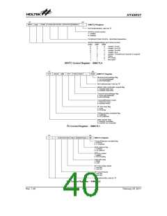
will be in a floating condition and the SPI operating
current will be reduced to a minimum value. When the
bit is high the SPI interface is enabled. The SIMconfig-
uration option must have first enabled the SIM inter-
face for this bit to be effective. Note that when the
SIMEN bit changes from low to high the contents of
the SPI control registers will be in an unknown condi-
tion and should therefore be first initialised by the ap-
plication program.
The SIMDR register is used to store the data being
transmitted and received. The same register is used by
both the SPI and I2 C functions. Before the
microcontroller writes data to the SPI bus, the actual
data to be transmitted must be placed in the SIMDR reg-
ister. After the data is received from the SPI bus, the
microcontroller can read it from the SIMDR register. Any
transmission or reception of data from the SPI bus must
be made via the SIMDR register.
·
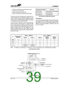
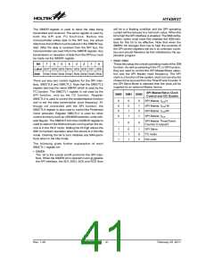
SIM0~SIM2
These bits setup the overall operating mode of the SIM
function. As well as selecting if the I2C or SPI function,
they are used to control the SPI Master/Slave selec-
tion and the SPI Master clock frequency. The SPI
clock is a function of the system clock but can also be
chosen to be sourced from the Timer/Event Counter. If
the SPI Slave Mode is selected then the clock will be
supplied by an external Master device.
Bit
7
6
5
4
3
2
1
0
Label SD7 SD6 SD5 SD4 SD3 SD2 SD1 SD0
R/W R/W R/W R/W R/W R/W R/W R/W R/W
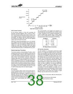
There are also two control registers for the SPI inter-
face, SIMCTL0 and SIMCTL2. Note that the SIMCTL2
register also has the name SIMAR which is used by the
I2C function. The SIMCTL1 register is not used by the
SPI function, only by the I2C function. Register
SIMCTL0 is used to control the enable/disable function
and to set the data transmission clock frequency. Al-
though not connected with the SPI function, the
SIMCTL0 register is also used to control the Peripheral
Clock prescaler. Register SIMCTL2 is used for other
control functions such as LSB/MSB selection, write colli-
sion flag etc. The SIMIDLE bit in the CLKMOD register is
used to select if the SIMcontinues running when the de-
vice is in the IDLE mode. Setting the bit high allows the
SIM to maintain operation when the device is in the Idle
mode. Clearing the bit to zero disables any SIMopera-
tions when in the Idle mode.
SPI Master/Slave Clock
SIM0 SIM1 SIM2
Control and I2C Enable
0
0
0
0
0
0
1
1
0
1
0
1
SPI Master, fSYS/4
SPI Master, fSYS/16
SPI Master, fSYS/64
SPI Master, fSUB
SPI Master Timer/Event
Counter 0 output/2
1
0
0
1
1
1
0
1
1
1
0
0
SPI Slave
I2C mode
Not used
The following gives further explanation of each
SIMCTL1 register bit:
·
SIMEN
The bit is the overall on/off control for the SPI inter-
face. When the SIMEN bit is cleared to zero to disable
the SPI interface, the SDI, SDO, SCK and SCS lines
Rev. 1.20
41
February 25, 2011
图片预览")
 HOLTEK [ HOLTEK SEMICONDUCTOR INC ]