HT45R37
For the PFD output to function, it is essential that the corre-
sponding bit of the Port Acontrol register PAC bit 3 is setup
as an output. If setup as an input the PFD output will not
function, however, the pin can still be used as a normal in-
put pin. The PFD output will only be activated if bit PA3 is
set to ²1². This output data bit is used as the on/off control
bit for the PFD output. Note that the PFD output will be low
if the PA3 output data bit is cleared to ²0².
register is full, the microcontroller will generate an inter-
nal interrupt signal directing the program flow to the re-
spective internal interrupt vector. For the pulse width
measurement mode, the internal system clock is also
used as the timer clock source but the timer will only run
when the correct logic condition appears on the external
timer input pin. As this is an external event and not syn-
chronized with the internal timer clock, the
microcontroller will only see this external event when the
next timer clock pulse arrives. As a result, there may be
small differences in measured values requiring program-
mers to take this into account during programming. The
same applies if the timer is configured to be in the event
counting mode, which again is an external event and not
synchronised with the internal system or timer clock.
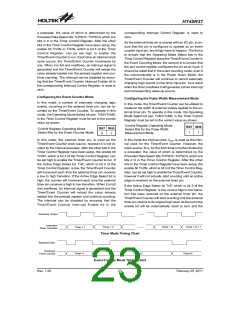
Using this method of frequency generation, and if a
crystal oscillator is used for the system clock, very pre-
cise values of frequency can be generated.
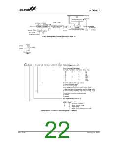
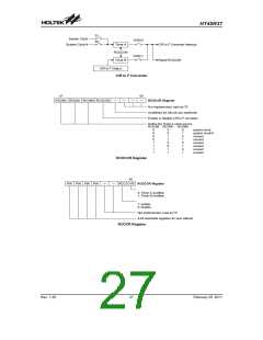
Prescaler
Bits TnPSC0~TnPSC2 of the control register can be
used to define the pre-scaling stages of the internal
clock source of the Timer/Event Counter. The
Timer/Event Counter overflow signal can be used to
generate signals for the PFD and Timer Interrupt.
When the Timer/Event Counter is read, or if data is writ-
ten to the preload register, the clock is inhibited to avoid
errors, however as this may result in a counting error, this
should be taken into account by the programmer. Care
must be taken to ensure that the timers are properly in-
itialised before using them for the first time. The associ-
ated timer enable bits in the interrupt control register must
be properly set otherwise the internal interrupt associated
with the timer will remain inactive. The edge select, timer
mode and clock source control bits in timer control regis-
ter must also be correctly set to ensure the timer is prop-
erly configured for the required application. It is also
important to ensure that an initial value is first loaded into
the timer registers before the timer is switched on; this is
because after power-on the initial values of the timer reg-
isters are unknown. After the timer has been initialised
the timer can be turned on and off by controlling the en-
able bit in the timer control register. Note that setting the
timer enable bit high to turn the timer on, should only be
executed after the timer mode bits have been properly
setup. Setting the timer enable bit high together with a
mode bit modification, may lead to improper timer oper-
ation if executed as a single timer control register byte
write instruction.
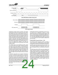
I/O Interfacing
The Timer/Event Counter, when configured to run in the
event counter or pulse width measurement mode, re-
quire the use of external pins for correct operation. As
these pins are shared pins they must be configured cor-
rectly to ensure they are setup for use as Timer/Event
Counter inputs and not as a normal I/O pins. This is im-
plemented by ensuring that the mode select bits in the
Timer/Event Counter control register, select either the
event counter or pulse width measurement mode. Addi-
tionally the Port Control Register must be set high to en-
sure that the pin is setup as an input. Any pull-high
resistor on these pins will remain valid even if the pin is
used as a Timer/Event Counter input.
Timer/Event Counter Pins Internal Filter
The external Timer/Event Counter pins are connected to
an internal filter to reduce the possibility of unwanted
event counting events or inaccurate pulse width mea-
surements due to adverse noise or spikes on the exter-
nal Timer/Event Counter input signal. As this internal
filter circuit will consume a limited amount of power, a
configuration option is provided to switch off the filter
function, an option which may be beneficial in power
sensitive applications, but in which the integrity of the in-
put signal is high. Care must be taken when using the fil-
ter on/off configuration option as it will be applied not
only to both external Timer/Event Counter pins but also
to the external interrupt input pins. Individual
Timer/Event Counter or external interrupt pins cannot
be selected to have a filter on/off function.
When the Timer/Event counter overflows, its corre-
sponding interrupt request flag in the interrupt control
register will be set. If the timer interrupt is enabled this
will in turn generate an interrupt signal. However irre-
spective of whether the interrupts are enabled or not, a
Timer/Event counter overflow will also generate a
wake-up signal if the device is in a Power-down condi-
tion. This situation may occur if the Timer/Event Counter
is in the Event Counting Mode and if the external signal
continues to change state. In such a case, the
Timer/Event Counter will continue to count these exter-
nal events and if an overflow occurs the device will be
woken up from its Power-down condition. To prevent
such a wake-up from occurring, the timer interrupt re-
quest flag should first be set high before issuing the
HALT instruction to enter the Power Down Mode.
Programming Considerations
When configured to run in the timer mode, the internal
system clock is used as the timer clock source and is
therefore synchronised with the overall operation of the
microcontroller. In this mode when the appropriate timer
Rev. 1.20
25
February 25, 2011
图片预览")
 HOLTEK [ HOLTEK SEMICONDUCTOR INC ]