HT45R37
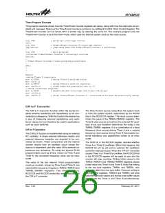
Timer Program Example
This program example shows how the Timer/Event Counter registers are setup, along with how the interrupts are en-
abled and managed. Note how the Timer/Event Counter is turned on, by setting bit 4 of the Timer Control Register. The
Timer/Event Counter can be turned off in a similar way by clearing the same bit. This example program sets the
Timer/Event Counter to be in the timer mode, which uses the internal system clock as the clock source.
org 04h
reti
; external interrupt vector
org 0Ch
jmp tmrint
:
; Timer/Event Counter 0 interrupt vector
; jump here when the Timer/Event Counter 0 overflows
org 20h ; main program
;internal Timer/Event Counter 0 interrupt routine
tmrint:
:
; Timer/Event Counter 0 main program placed here
:
reti
:
:
begin:
;setup Timer 0 registers
mov a,09bh
mov tmr0,a;
mov a,081h
mov tmr0c,a
; setup Timer 0 preload value
; setup Timer 0 control register
; timer mode and prescaler set to /2
; setup interrupt register
mov a,009h
mov int0c,a
set tmr0c.4
; enable master interrupt and timer interrupt
; start Timer/Event Counter 0 - note mode bits must be previously setup
C/R to F Converter
The C/R to F Converter function within the device en-
ables external resistance and capacitance to be con-
verted into a frequency. With this function the device has
a way of measuring external capacitance and resis-
tance values and can therefore be used in applications
such as touch switches.
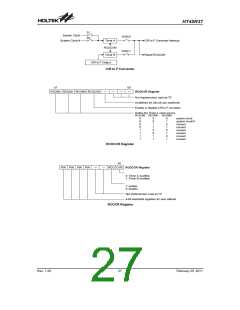
The Timer A clock source comes from the system clock
or from the system clock/4, determined by the RCOM
bits in the RCOCCR register. This clock source deter-
mines the value in the TMRAL/TMRAH registers. The
Timer B clock source comes from the external RC oscil-
lator circuit and therefore determines the value in the
TMRBL/TMRBL registers. It is a combination of a fixed
frequency clock source driving Timer A and a varying
frequency clock source driving Timer B that enables ex-
ternal resistance and capacitance values to be mea-
sured.
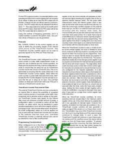
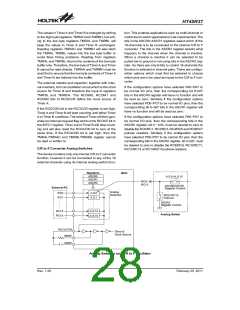
C/R to F Operation
The C/R to F function is implemented using an external
RC oscillator. A single external reference resistor and
external reference capacitor are required to be con-
nected as shown. These components and the internal
inverter circuits form an oscillator circuit whose fre-
quency is dependent upon the value of the external ca-
pacitance and resistance. By using two internal 16-bit
programmable count-up timers, known as Timer A and
Timer B, the converted frequency value can be mea-
sured.
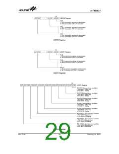
The OVB bit, in the RCOCR register, decides whether
Timer A or Timer B overflows. When this happens, the
RCOCF bit will be set and an external RC oscillation
converter interrupt occurs. When the C/R to F converter
causes Timer A or Timer B to overflow, the RCOCON bit
in the RCOCCR register will be reset to zero and the
counter will stop counting. Writing initial values to the
TMRAL/TMRAH and TMRBL/TMRBH registers places
a start value into Timer A and Timer B. Note that writing
to the low byte registers, TMRAL and TMRBL, only
writes the data into a low byte buffer. However writing to
the high byte registers, TMRAH and TMRBH, will write
both the high byte values and the low byte buffer values
directly into the Timer A and Timer B simultaneously.
The value of the two internal 16-bit programmable
count-up counters, known as Timer A and Timer B, are
stored within two pairs of registers, TMRAL/TMRAH and
TMRBL/TMRBH registers. Two other registers,
RCOCCR and RCOCR control the overall operation of
the C/R to F converter.
Rev. 1.20
26
February 25, 2011
图片预览")
 HOLTEK [ HOLTEK SEMICONDUCTOR INC ]