HT37B90/HT37B70/HT37B50/HT37B30
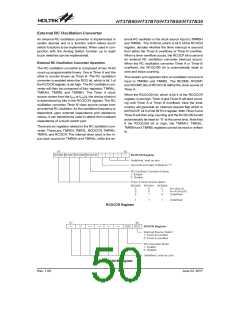
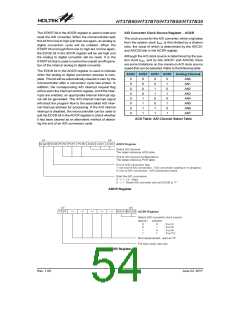
A/D Converter Clock Source Register - ACSR
The START bit in the ADCR register is used to start and
reset the A/D converter. When the microcontroller sets
this bit from low to high and then low again, an analog to
digital conversion cycle will be initiated. When the
START bit is brought from low to high but not low again,
the EOCB bit in the ADCR register will be set high and
the analog to digital converter will be reset. It is the
START bit that is used to control the overall on/off opera-
tion of the internal analog to digital converter.
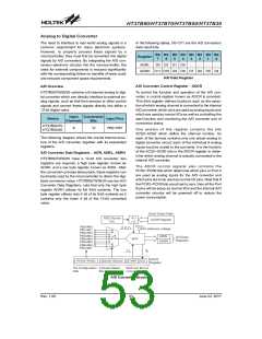
The clock source for the A/D converter, which originates
from the system clock fOSC, is first divided by a division
ratio, the value of which is determined by the ADCS1
and ADCS0 bits in the ACSR register.
Although the A/D clock source is determined by the sys-
tem clock fOSC, and by bits ADCS1 and ADCS0, there
are some limitations on the maximum A/D clock source
speed that can be selected. Refer to the following table.
The EOCB bit in the ADCR register is used to indicate
when the analog to digital conversion process is com-
plete. This bit will be automatically cleared to zero by the
microcontroller after a conversion cycle has ended. In
addition, the corresponding A/D interrupt request flag
will be set in the interrupt control register, and if the inter-
rupts are enabled, an appropriate internal interrupt sig-
nal will be generated. This A/D internal interrupt signal
will direct the program flow to the associated A/D inter-
nal interrupt address for processing. If the A/D internal
interrupt is disabled, the microcontroller can be used to
poll the EOCB bit in the ADCR register to check whether
it has been cleared as an alternative method of detect-
ing the end of an A/D conversion cycle.
ACS3 ACS2 ACS1 ACS0 Analog Channel
0
0
0
0
0
0
0
0
0
0
0
0
1
1
1
1
0
0
1
1
0
0
1
1
0
1
0
1
0
1
0
1
AN0
AN1
AN2
AN3
AN4
AN5
AN6
AN7
ACS Table: A/D Channel Select Table
ADCR Register
ACSR Register
Rev. 1.00
54
June 22, 2017

 HOLTEK [ HOLTEK SEMICONDUCTOR INC ]