HT37B90/HT37B70/HT37B50/HT37B30
Accumulator - ACC
Bank Pointer - RBP1, RBP2
The Accumulator is central to the operation of any
microcontroller and is closely related with operations
carried out by the ALU. The Accumulator is the place
where all intermediate results from the ALU are stored.
Without the Accumulator it would be necessary to write
the result of each calculation or logical operation such
as addition, subtraction, shift, etc., to the Data Memory
resulting in higher programming and timing overheads.
Data transfer operations usually involve the temporary
storage function of the Accumulator; for example, when
transferring data between one user defined register and
another, it is necessary to do this by passing the data
through the Accumulator as no direct transfer between
two registers is permitted.
The RAM Data Memory is divided into 8 Banks, known as
Bank 0 to Bank 7. Selecting the required Data Memory
area is achieved using the RAM Bank Pointers which are
RBP1 and RBP2. The RBP1 and RBP2 match up with
MP1 and MP2 respectively. If data in Bank 0 is to be ac-
cessed, then the RBP registers must be loaded with the
value ²00², while if data in Bank 1 is to be accessed, then
the RBP registers must be loaded with the value ²01².
Register IAR0 will always access data from Bank 0, irre-
spective of the value of the Bank Pointer. The RBP1 and
RBP2 register is located at memory location 60H in
Bank 0 to Bank 7 and can only be accessed indirectly
using two memory pointers MP1 and MP2 and the indi-
rect addressing register IAR1 will always access data
from Bank 0 to Bank 7.
Program Counter Low Register - PCL
The Data Memory is initialized to Bank 0 after a reset,
except for the WDT time-out reset in the Power Down
Mode, in which case, the Data Memory bank remains
unaffected. It should be noted that Special Function
Data Memory is not affected by the bank selection,
which means that the Special Function Registers can be
accessed from within Bank 0 to Bank 7. Directly ad-
dressing the Data Memory will always result in Bank 0
being accessed irrespective of the value of the Bank
Pointer.
To provide additional program control functions, the low
byte of the Program Counter is made accessible to pro-
grammers by locating it within the Special Purpose area
of the Data Memory. By manipulating this register, direct
jumps to other program locations are easily imple-
mented. Loading a value directly into this PCL register
will cause a jump to the specified Program Memory lo-
cation, however, as the register is only 8-bit wide, only
jumps within the current Program Memory page are per-
mitted. When such operations are used, note that a
dummy cycle will be inserted.
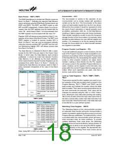
Register
Bit No.
Function
RAM Bank Point 1 Select
000= Select RAM Bank0
001= Select RAM Bank1
010= Select RAM Bank2
011= Select RAM Bank3
100= Select RAM Bank4
101= Select RAM Bank5
110= Select RAM Bank6
111= Select RAM Bank7
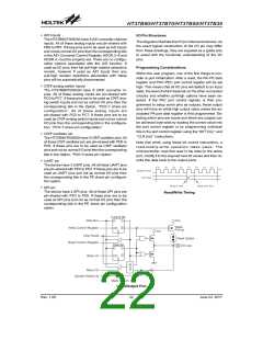
Look-up Table Registers - TBLP1, TBMP1, TBHP1,
TBLH
These seven special function registers are used to con-
trol operation of the look-up table which is stored in the
Program Memory. TBLP1, TBMP1 and TBHP1 are the
table pointer and indicate the location where the table
data is located. Their value must be setup before any ta-
ble read commands are executed. Their value can be
changed, for example using the ²INC² or ²DEC² instruc-
tions, allowing for easy table data pointing and reading.
TBLH is the location where the high order byte of the ta-
ble data is stored after a table read data instruction has
been executed. Note that the lower order table data byte
is transferred to a user defined location.
0~2
RBP1
General bits. Can write and
read.
3~4
5~7
Unused bit
RBP1 (04H)
Register
Bit No.
Function
RAM Bank Point 2 Select
000= Select RAM Bank0
001= Select RAM Bank1
010= Select RAM Bank2
011= Select RAM Bank3
100= Select RAM Bank4
101= Select RAM Bank5
110= Select RAM Bank6
111= Select RAM Bank7
Watchdog Timer Register - WDTS
The Watchdog feature of the microcontroller provides
an automatic reset function giving the microcontroller a
means of protection against spurious jumps to incorrect
Program Memory addresses. To implement this, a timer
is provided within the microcontroller which will issue a
reset command when its value overflows. To provide
variable Watchdog Timer reset times, the Watchdog
Timer clock source can be divided by various division ra-
tios, the value of which is set using the WDTS register.
By writing directly to this register, the appropriate divi-
sion ratio for the Watchdog Timer clock source can be
0~2
RBP2
General bits. Can write and
read.
3~4
5~7
Unused bit
RBP2 (2FH)
Note: Using MP1 or MP2 are selected by DACC.7.
Rev. 1.00
18
June 22, 2017

 HOLTEK [ HOLTEK SEMICONDUCTOR INC ]