HT37B90/HT37B70/HT37B50/HT37B30
²CLR WDT² or ²HALT² instruction. TO is set by a
WDT time-out.
setup. Note that only the lower 3 bits are used to set divi-
sion ratios between 1 and 128.
In addition, on entering an interrupt sequence or execut-
ing a subroutine call, the status register will not be
pushed onto the stack automatically. If the contents of
the status registers are important and if the subroutine
can corrupt the status register, precautions must be
taken to correctly save it.
Status Register - STATUS
This 8-bit register contains the zero flag (Z), carry flag
(C), auxiliary carry flag (AC), overflow flag (OV), power
down flag (PDF), and watchdog time-out flag (TO).
These arithmetic/logical operation and system manage-
ment flags are used to record the status and operation of
the microcontroller.
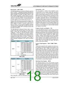
Interrupt Control Registers - INTC, INTCH
The two 8-bit registers, known as the INTC and INTCH
register which control the operation of both external and
internal timer, UART, CR/F and ADPCM interrupts, and
By setting various bits within this register using standard
bit manipulation instructions, the enable/disable func-
tion of the external and timer, UART, CR/F and ADPCM
interrupts can be independently controlled. A master in-
terrupt bit within this register, the EMI bit, acts like a
global enable/disable and is used to set all of the inter-
rupt enable bits on or off. This bit is cleared when an in-
terrupt routine is entered to disable further interrupt and
is set by executing the ²RETI² instruction.
With the exception of the TO and PDF flags, bits in the
status register can be altered by instructions like most
other registers. Any data written into the status register
will not change the TO or PDF flag. In addition, opera-
tions related to the status register may give different re-
sults due to the different instruction operations. The TO
flag can be affected only by a system power-up, a WDT
time-out or by executing the ²CLR WDT² or ²HALT² in-
struction. The PDF flag is affected only by executing the
²HALT² or ²CLR WDT² instruction or during a system
power-up.
The Z, OV, AC and C flags generally reflect the status of
the latest operations.
Note: In situations where other interrupts may require
servicing within present interrupt service rou-
tines, the EMI bit can be manually set by the
program after the present interrupt service rou-
tine has been entered.
·
C is set if an operation results in a carry during an ad-
dition operation or if a borrow does not take place dur-
ing a subtraction operation; otherwise C is cleared. C
is also affected by a rotate through carry instruction.
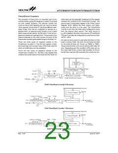
Timer/Event Counter Registers - TMR0H, TMR0L,
TMR1L, TMR2L, TMR0C, TMR1C, TMR2C
·
AC is set if an operation results in a carry out of the
low nibbles in addition, or no borrow from the high nib-
ble into the low nibble in subtraction; otherwise AC is
cleared.
HT37B90/70/50/30 contains two 8-bit and a 16-bit
Timer/Event Counters which has an associated register
known as TMR0H and TMR0L. are the location where
the timer¢s 16-bit value is located.TMR1L and TMR2L
are the location where the timer¢s 8-bit value is located.
An associated control register, known as TMR0C,
TMR1C and TMR2C contains the setup information for
the timer.
·
·
Z is set if the result of an arithmetic or logical operation
is zero; otherwise Z is cleared.
OV is set if an operation results in a carry into the high-
est-order bit but not a carry out of the highest-order bit,
or vice versa; otherwise OV is cleared.
·
·
PDF is cleared by a system power-up or executing the
²CLR WDT² instruction. PDF is set by executing the
²HALT² instruction.
TO is cleared by a system power-up or executing the
Status Register
Rev. 1.00
19
June 22, 2017

 HOLTEK [ HOLTEK SEMICONDUCTOR INC ]