HT37B90/HT37B70/HT37B50/HT37B30
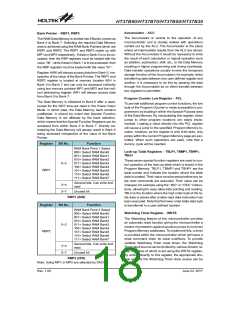
ROM Bank Pointer (2DH)
The program memory is organized into 64/32/16/8 banks for HT37B90/70/50/30 and each bank into 8K´16 bits of pro-
gram ROM. BP1.7~BP1.0 is used as the bank pointer. After an instruction has been executed to write data to the BP1
register to select a different bank, note that the new bank will not be selected immediately. It is until the instruction
²JMP² or ²CALL² or interrupt has completed execution that the bank will be actually selected.
Register
Bit No.
Function
00000000b= Select ROM Bank0 (0000h~1FFFh)
00000001b= Select ROM Bank1 (2000h~3FFFh)
00000010b= Select ROM Bank2 (4000h~5FFFh)
00000011b= Select ROM Bank3 (6000h~7FFFh)
:
BP1 (2DH)
0~7
00011110b= Select ROM Bank30 (3C000h~3DFFFh)
00011111b= Select ROM Bank31 (3E000h~3FFFFh)
00111110b= Select ROM Bank62 (7C000h~7DFFFh)
00111111b= Select ROM Bank63 (7E000h~7FFFFh)
Note: For the HT37B90, the ROM bank point register is 6 bits wide effectively, i.e. from b5~b0.
For the HT37B70, the ROM bank point register is 5 bits wide effectively, i.e. from b4~b0.
For the HT37B50, the ROM bank point register is 4 bits wide effectively, i.e. from b3~b0.
For the HT37B30, the ROM bank point register is 3 bits wide effectively, i.e. from b2~b0.
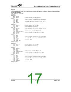
RAM Data Memory
The RAM Data Memory is a volatile area of 8-bit wide
RAM internal memory and is the location where
temporary information is stored. Divided into two
sections, the first of these is an area of RAM where
special function registers are located. These registers
have fixed locations and are necessary for correct
operation of the device.
protected from user manipulation. The second area of
RAM Data Memory is reserved for general purpose use.
All locations within this area are read and write accessi-
ble under program control.
Structure
The RAM Data Memory is subdivided into 4 or 8 banks,
known as Bank 0 to Bank 3 or Bank 7, all of which are
implemented in 8-bit wide RAM. Most of the RAM Data
Memory is located in Bank 0 which is also subdivided
into two sections, the Special Purpose Data Memory
and the General Purpose Data Memory. The start ad-
dress of the Data Memory is the address ²00H². Regis-
ters which are common to all microcontrollers, such as
ACC, PCL, etc., have the same Data Memory address.
Bank 1 of the RAM Data Memory is located at address
²60H².
Many of these registers can be read from and written to
directly under program control, however, some remain
The RAM data memory is designed with 640´8 bits or
1280´8 bits with 4 or 8 RAM banks. There are two RAM
BANK pointers (RBP1 and RBP2 ) control Bank 0~7.
Bank 0~Bank 3 RAM Data Memory Structure -
HT37B70/50/30
The data memory is designed with 256 bytes and di-
vided into five functional groups: special function regis-
ters (00H~1FH), music synthesis controller registers
(20H~2FH), ADPCM decoder controller register
(30H~35H), the other function (35H~5FH) and general
purpose data memory (60H~FFH).
They are also indirectly accessible through Memory
Bank 0~Bank 7 RAM Data Memory Structure -
HT37B90
Rev. 1.00
14
June 22, 2017

 HOLTEK [ HOLTEK SEMICONDUCTOR INC ]