HT36M4
layed by one more cycle. If the wake-up results in next
instruction execution, this will be executed immediately
after a dummy period has finished. If an interrupt request
flag is set to ²1² before entering the HALT mode, the
wake-up function of the related interrupt will be disabled.
instruction. The software instructions include ²CLR
WDT² and the other set - ²CLR WDT1² and ²CLR
WDT2². Of these two types of instructions, only one can
be active depending on the mask option - ²CLR WDT
times selection option². If the ²CLR WDT² is selected
(i.e. CLRWDT times equal one), any execution of the
²CLR WDT² instruction will clear the WDT. In case ²CLR
WDT1² and ²CLR WDT2² are chosen (i.e. CLRWDT
times equal two), these two instructions must be exe-
cuted to clear the WDT; otherwise, the WDT may reset
the chip due to time-out.
To minimize power consumption, all I/O pins should be
carefully managed before entering the HALT status.
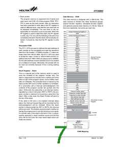
Reset
There are three ways in which a reset can occur:
·
·
·
RES reset during normal operation
RES reset during HALT
Power Down Operation - HALT
WDT time-out reset during normal operation
The HALT mode is initialized by a HALT instruction and
results in the following:
The WDT time-out during HALT is different from other
chip reset conditions, since it can perform a ²warm re -
set² that resets the Program Counter and Stack Pointer,
leaving the other circuits in their original state. Some
registers remain unchanged during other reset condi-
tions. Most registers are reset to the ²initial condition²
when the reset conditions are met. By examining the
PDF and TO flags, the program can distinguish between
different ²chip resets².
·
The system oscillator will turn off but the WDT oscilla-
tor keeps running (if the WDT oscillator is selected).
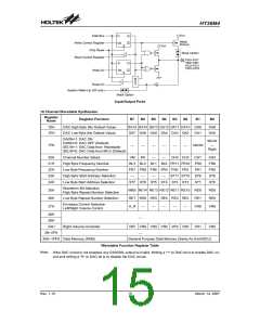
Watchdog Timer - WDT
·
·
The contents of the on-chip RAM and registers remain
unchanged.
The WDT and WDT prescaler will be cleared and
starts to count again (if the clock comes from the WDT
oscillator).
·
·
·
All I/O ports maintain their original status.
V
D
D
The PDF flag is set and the TO flag is cleared.
R
E
S
t
S S T
The HALT pin will output a high level signal to disable
the external ROM.
S
S
T
T
i
m
e
-
o
u
t
The system can leave the HALT mode by means of an
external reset, an interrupt, an external falling edge sig-
nal on port A or a WDT overflow. An external reset
causes a device initialization and the WDT overflow per-
forms a ²warm reset². By examining the TO and PDF
flags, the cause for a chip reset can be determined. The
PDF flag is cleared when there is a system power-up or by
executing the ²CLR WDT² instruction and it is set when a
HALT instruction is executed. The TO flag is set if a WDT
time-out occurs, and causes a wake-up that only resets
the Program Counter and Stack Pointer, the others remain
in their original status.
C
h
i
p
R
e
s
e
t
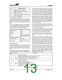
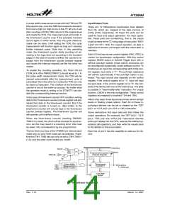
Reset Timing Chart
V
D
D
R
E
S
The port A wake-up and interrupt methods can be con-
sidered as a continuation of normal execution. Each bit
in port A can be independently selected to wake-up the
device by mask option. Awakening from an I/O port stim-
ulus, the program will resume execution of the next in-
struction. If awakening from an interrupt, two sequences
may occur. If the related interrupts is disabled or the in-
terrupts is enabled but the stack is full, the program will
resume execution at the next instruction. If the interrupt
is enabled and the stack is not full, a regular interrupt re-
sponse takes place.
Reset Circuit
H
A
L
T
W
a
r
m
R
e
s
e
t
W
T
D
T
e
W
D
T
i
m
-
o
u
t
R
e
s
e
t
R
E
S
C
o
l
d
S
S
T
R
e
s
e
t
1
0
-
s
t
a
g
e
O
S
C
I
R
i
p
p
l
e
C
o
u
n
t
e
r
Once a wake-up event occurs, it takes 1024 tSYS (system
clock period) to resume to normal operation. In other
words, a dummy cycle period will be inserted after a
wake-up. If the wake-up results from an interrupt ac-
knowledge, the actual interrupt subroutine will be de-
P
o
w
e
r
-
o
n
D
e
t
e
c
t
i
n
g
Reset Configuration
Rev. 1.10
11
March 14, 2007

 HOLTEK [ HOLTEK SEMICONDUCTOR INC ]