HT36M4
In pulse width measurement mode with the TON and TE
bits equal to one, once the TMR has received a transient
from low to high (or high to low; if the TE bit is 0) it will
start counting until the TMR returns to the original level
and resets the TON. The measured result will remain in
the timer/event counter even if the activated transient
occurs again. In other words, only one cycle measure-
ments can be done. Until setting the TON, the cycle
measurement will function again as long as it receives
further transient pulse. Note that, in this operating
mode, the timer/event counter starts counting not ac-
cording to the logic level but according to the transient
edges. In the case of counter overflow, the counter is re-
loaded from the timer/event counter preload register
and issues the interrupt request just like the other two
modes.
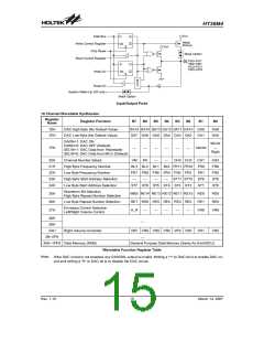
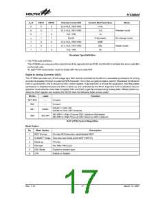
Input/Output Ports
There are 12 bidirectional input/output lines labeled
from PA, which are mapped to the data memory of
[12H], [14H] respectively. All these I/O ports can be
used for input and output operations. For input opera-
tion, these ports are non-latching, that is, the inputs
must be ready at the T2 rising edge of instruction ²MOV
A,[m]² (m=12H, 14H). For output operation, all data is
latched and remains unchanged until the output latch is
rewritten.
Each I/O line has its own control register (PAC, PBC) to
control the input/output configuration. With this control
register, CMOS output or Schmitt Trigger input with or
without pull-high resistor (mask option) structures can
be reconfigured dynamically under software control. To
function as an input, the corresponding latch of the con-
trol register must write a ²1². The pull-high resistance
will exhibit automatically if the pull-high option is se-
lected. The input source also depends on the control
register. If the control register bit is ²1², input will read
the pad state. If the control register bit is ²0², the con-
tents of the latches will move to the internal bus. The latter
is possible in ²read-modify-write² instruction. For output
function, CMOS is the only configuration. These control
registers are mapped to locations 13H and 15H).
To enable the counting operation, the Timer ON bit
(TON; bit 4 of the TMR0C/TMR1C) should be set to 1. In
the pulse width measurement mode, the TON will be
cleared automatically after the measurement cycle is
completed. But in the other two modes the TON can only
be reset by instruction. The overflow of the timer/event
counter is one of the wake-up sources. No matter what
the operation mode is, writing a 0 to ET0I/ET1I can dis-
able the corresponding interrupt service.
In the case of timer/event counter OFF condition, writing
data to the Timer/event counter preload register will also
reload that data to the timer/event counter. But if the
timer/event counter is turned on, data written to the
timer/event counter will only be kept in the timer/event
counter preload register. The timer/event counter will
still operate until overflow occurs.
After a chip reset, these input/output lines remain at high
levels or floating (mask option). Each bit of these in-
put/output latches can be set or cleared by the ²SET
[m].i² or ²CLR [m].i² (m=12H or 14H) instruction.
Some instructions first input data and then follow the
output operations. For example, the ²SET [m].i², ²CLR
[m].i², ²CPL [m]² and ²CPLA [m]² instructions read the
entire port states into the CPU, execute the defined op-
erations (bit-operation), and then write the results back
to the latches or the accumulator.
When the timer/event counter (reading TMR0H/
TMR1H) is read, the clock will be blocked to avoid er-
rors. As this may result in a counting error, this must
be taken into consideration by the programmer.
The two timer counters of the HT36M4 are internal clock
mode only, so only Timer mode can be selected. There-
fore the (TM1, TM0) bits can only be set to (TM1,TM0) =
(1,0), and the other clock modes are invalid.
Each line of port A has the capability to wake-up the de-
vice.
D
a
t
a
B
u
s
O
S
C
T
M
1
R
e
l
o
a
d
T
M
0
T
i
m
e
r
/
e
v
e
n
t
C
o
u
n
t
e
r
0
P
r
e
l
o
a
d
R
e
g
i
s
t
e
r
G
N
D
T
E
T
i
m
e
r
/
e
v
e
n
t
P
u
l
s
e
W
i
d
t
h
O
v
e
r
f
l
o
w
T
M
1
C
o
u
n
t
e
r
0
M
e
a
s
u
r
e
m
e
n
t
T
o
I
n
t
e
r
r
u
p
t
T
M
0
M
o
d
e
C
o
n
t
r
o
l
T
O
N
L
o
w
B
y
t
e
B
u
f
f
e
r
Timer/Event Counter 0/1
Rev. 1.10
14
March 14, 2007

 HOLTEK [ HOLTEK SEMICONDUCTOR INC ]