HT36M4
Interrupt
The Timer/Event Counter 1 interrupt is operated in the
same manner as Timer/Event Counter 0. The related in-
terrupt control bits ET1I and T1F of the Timer/Event
Counter 1 are bit 3 and bit 6 of the INTC respectively.
The HT36M4 provides two internal timer/event counter
interrupts on each bank. The Interrupt Control register
(INTC;0BH) contains the interrupt control bits that sets
the enable/disable and the interrupt request flags.
During the execution of an interrupt subroutine, other in-
terrupt acknowledgments are held until the RETI in-
struction is executed or the EMI bit and the related
interrupt control bit are set to 1 (if the stack is not full). To
return from the interrupt subroutine, the RET or RETI in-
struction may be invoked. RETI will set the EMI bit to en-
able an interrupt service, but RET will not.
Once an interrupt subroutine is serviced, all other inter-
rupts will be blocked (by clearing the EMI bit). This
scheme may prevent any further interrupt nesting. Other
interrupt requests may occur during this interval but only
the interrupt request flag is recorded. If a certain inter-
rupt needs servicing within the service routine, the pro-
grammer may set the EMI bit and the corresponding bit
of the INTC to allow interrupt nesting. If the stack is full,
the interrupt request will not be acknowledged, even if
the related interrupt is enabled, until the stack pointer is
decremented. If immediate service is desired, the stack
must be prevented from becoming full.
Interrupts occurring in the interval between the rising
edges of two consecutive T2 pulses, will be serviced on
the latter of the two T2 pulses, if the corresponding inter-
rupts are enabled. In the case of simultaneous requests
the priorities in the following table apply. These can be
masked by resetting the EMI bit.
All these kinds of interrupt have a wake-up capability. As
an interrupt is serviced, a control transfer occurs by
pushing the program counter onto the stack and then
branching to subroutines at specified locations in the
program memory. Only the program counter is pushed
onto the stack. If the contents of the register and Status
register (STATUS) are altered by the interrupt service
program which may corrupt the desired control se-
quence, then the programmer must save the contents
first.
Interrupt Source
Priority Vector
Timer/Event Counter 0 overflow
Timer/Event Counter 1 overflow
1
2
08H
0CH
Once the interrupt request flags (T0F, T1F) are set, they
will remain in the INTC register until the interrupts are
serviced or cleared by a software instruction. It is
recommended that a program does not use the ²CALL
subroutine² within the interrupt subroutine. Because in-
terrupts often occur in an unpredictable manner or need
to be serviced immediately in some applications, if only
one stack is left and enabling the interrupt is not well
controlled, once the ²CALL subroutine² operates in the in-
terrupt subroutine, it may damage the original control
sequence.
The internal Timer/Event Counter 0 interrupt is initial-
ized by setting the Timer/Event Counter 0 interrupt re-
quest flag (T0F; bit 5 of the INTC), caused by a
Timer/Event Counter 0 overflow. When the interrupt is
enabled, and the stack is not full and the T0F bit is set, a
subroutine call to location 08H will occur. The related in-
terrupt request flag (T0F) will be reset and the EMI bit
cleared to disable further interrupts.
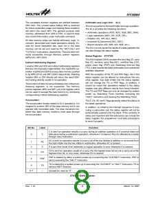
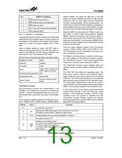
Bit No.
Label
EMI
EEI
Function
0
1
2
3
4
5
6
7
Controls the Master (Global) interrupt (1=enable; 0=disable)
Control the external interrupt (1=enable; 0=disable)
Controls the Timer/Event Counter 0 interrupt (1=enable; 0=disable)
Controls the Timer/Event Counter 1 interrupt (1=enable; 0=disable)
External interrupt request flag (1=active; 0=inactive)
Internal Timer/Event Counter 0 request flag (1=active; 0=inactive)
Internal Timer/Event Counter 1 request flag (1=active; 0=inactive)
Unused bit, read as ²0²
ET0I
ET1I
EEO
T0F
T1F
¾
INTC (0BH) Register
Rev. 1.10
9
March 14, 2007

 HOLTEK [ HOLTEK SEMICONDUCTOR INC ]