HT16C21
Command Summary
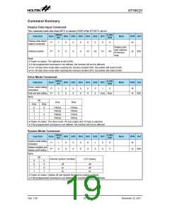
Display Data Input Command
This command sends data from MCU to memory MAP of the HT16C21 device.
(MSB)
Bit7
(LSB)
Bit0
Function
Byte
Bit6 Bit5 Bit4 Bit3 Bit2 Bit1
Note
R/W Def
Display data input/
output command
1st
1
0
0
0
0
0
0
0
W
Display data
start address
of memory
map
Address pointer
Note:
2nd
X
X
X
X
A3
A2
A1
A0
W
00H
● Power on status: The address is set to 00H.
● If the programmed command is not defined, the function will not be affected.
● For 1/4 duty drive mode after reaching the memory location 09H, the pointer will reset to 00H.
● For 1/8 duty drive mode after reaching the memory location 0FH, the pointer will reset to 00H.
Drive Mode Command
(MSB)
Bit7
(LSB)
Bit0
Function
Byte
Bit6 Bit5 Bit4 Bit3 Bit2 Bit1
Note
R/W Def
Driver mode setting
command
1st
1
0
0
0
0
0
1
0
W
Duty and bias setting 2nd
X
X
X
X
X
X
Duty Bias
W
00H
Note:
Bit
Duty
Bias
Duty
Bias
0
0
1
1
0
1
0
1
1/4duty
1/4duty
1/8duty
1/8duty
1/3bias
1/4bias
1/3bias
1/4bias
● Power on status: The drive mode 1/4 duty output and 1/3 bias is selected.
● If the programmed command is not defined, the function will not be affected.
System Mode Command
(MSB)
Bit7
(LSB)
Bit0
Function
Byte
1st
Bit6 Bit5 Bit4 Bit3 Bit2 Bit1
Note
R/W Def
System mode setting
command
1
0
0
0
0
1
0
0
W
System oscillator and
display on/off setting
2nd
X
X
X
X
X
X
S
E
W
00H
Note:
Bit
Internal System Oscillator
LCD Display
S
0
1
1
E
X
0
1
off
on
on
off
off
on
● Power on status: Display off and disable the internal system oscillator.
● If the programmed command is not defined, the function will not be affected.
Rev. 1.00
19
November 22, 2011

 HOLTEK [ HOLTEK SEMICONDUCTOR INC ]