HT16C21
I2C Serial Interface
I2C Operation
The device supports I2C serial interface. The I2C interface is for bidirectional, two-line communication between
different ICs or modules. The two lines are a serial data line, SDA, and a serial clock line, SCL. Both lines are
connected to the positive supply via pull-up resistors with a typical value of 4.7KΩ. When the I2C interface is
free, both lines are high. Devices connected to the I2C interface must have open-drain or open-collector outputs to
implement a wired-or function. Data transfer is initiated only when the I2C interface is not busy.
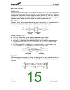
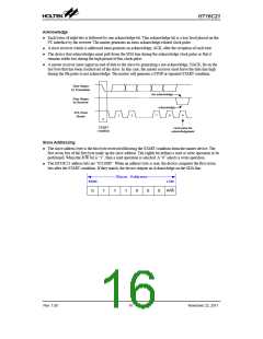
Data Validity
The data on the SDA line must be stable during the high period of the serial clock. The high or low state of the
data line can only change when the clock signal on the SCL line is Low as shown in the diagram.
SDA
SCL
Data line stable;
Data valid
Change of data
allowed
START and STOP Conditions
A high to low transition on the SDA line while SCL is high defines a START condition.
●
●
●
A low to high transition on the SDA line while SCL is high defines a STOP condition.
START and STOP conditions are always generated by the master. The I2C interface is considered to be busy
after the START condition. The I2C interface is considered to be free again a certain time after the STOP
condition.
The I2C interface stays busy if a repeated START (Sr) is generated instead of a STOP condition. In some
respects, the START(S) and repeated START (Sr) conditions are functionally identical.
●
SDA
SCL
SDA
SCL
S
P
START condition
STOP condition
Byte Format
Every byte put on the SDA line must be 8-bit long. The number of bytes that can be transmitted per transfer is
unrestricted. Each byte has to be followed by an acknowledge bit. Data is transferred with the most significant bit,
MSB, first.
P
SDA
Sr
SCL
S
P
1
2
7
8
9
1
2
3-8
9
or
Sr
or
Sr
ACK
ACK
Rev. 1.00
15
November 22, 2011

 HOLTEK [ HOLTEK SEMICONDUCTOR INC ]