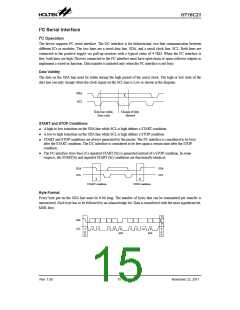
HT16C21
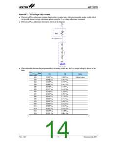
Internal VLCD Voltage Adjustment
The internal VLCD adjustment contains four resistors in series and a 4-bit programmable analog switch which
can provide sixteen voltage adjustment options using the VLCD voltage adjustment command.
●
The internal VLCD adjustment structure is shown in the diagram:
●
V
DD
IVA
V
LCD pin
R
R
R
R
LCD Bias
generator
The relationship between the programmable 4-bit analog switch and the VLCD output voltage is shown in the
table:
●
Bias
1/3
1/4
Note
DA3~DA0
00H
1.000*VDD
0.944*VDD
0.894*VDD
0.849*VDD
0.808*VDD
0.771*VDD
0.738*VDD
0.707*VDD
0.678*VDD
0.652*VDD
0.628*VDD
0.605*VDD
0.584*VDD
0.565*VDD
0.547*VDD
0.529*VDD
1.000*VDD
0.957*VDD
0.918*VDD
0.882*VDD
0.849*VDD
0.818*VDD
0.789*VDD
0.763*VDD
0.738*VDD
0.714*VDD
0.692*VDD
0.672*VDD
0.652*VDD
0.634*VDD
0.616*VDD
0.600*VDD
Default value
01H
02H
03H
04H
05H
06H
07H
08H
09H
0AH
0BH
0CH
0DH
0EH
0FH
Rev. 1.00
14
November 22, 2011

 HOLTEK [ HOLTEK SEMICONDUCTOR INC ]