HT46R4A
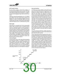
Another reset exists in the form of a Low Voltage Reset,
LVR, where a full reset, similar to the RES reset is imple-
mented in situations where the power supply voltage
falls below a certain threshold.
m
0 . 0 1 F
V
R
D
D
S
1
0
0
k
E
1
0
k
Reset Functions
m
0 . 1 F
There are five ways in which a microcontroller reset can
occur, through events occurring both internally and ex-
ternally:
V
S
S
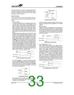
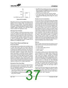
Enhanced Reset Circuit
·
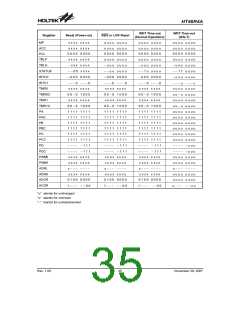
Power-on Reset
More information regarding external reset circuits is
located in Application Note HA0075E on the Holtek
website.
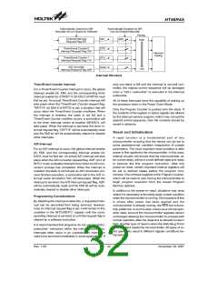
The most fundamental and unavoidable reset is the
one that occurs after power is first applied to the
microcontroller. As well as ensuring that the Program
Memory begins execution from the first memory ad-
dress, a power-on reset also ensures that certain
other registers are preset to known conditions. All the
I/O port and port control registers will power up in a
high condition ensuring that all pins will be first set to
inputs.
·
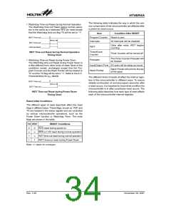
RES Pin Reset
This type of reset occurs when the microcontroller is
already running and the RES pin is forcefully pulled
low by external hardware such as an external switch.
In this case as in the case of other reset, the Program
Counter will reset to zero and program execution initi-
ated from this point.
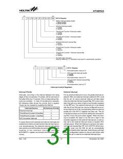
Although the microcontroller has an internal RC reset
function, if the VDD power supply rise time is not fast
enough or does not stabilise quickly at power-on, the
internal reset function may be incapable of providing
proper reset operation. For this reason it is recom-
mended that an external RC network is connected to
the RES pin, whose additional time delay will ensure
that the RES pin remains low for an extended period
to allow the power supply to stabilise. During this time
delay, normal operation of the microcontroller will be
inhibited. After the RES line reaches a certain voltage
value, the reset delay time tRSTD is invoked to provide
an extra delay time after which the microcontroller will
begin normal operation. The abbreviation SST in the
figures stands for System Start-up Timer.
0
.
9
V
0
.
4
V
R
E
S
t
R S T D
S
S
T
T
i
m
e
-
o
u
t
t
I
n
t
e
r
n
a
l
R
e
s
e
RES Reset Timing Chart
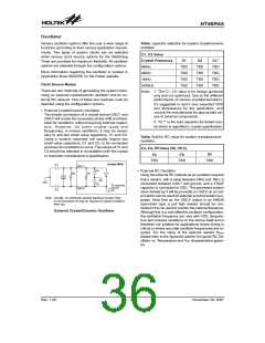
Low Voltage Reset - LVR
·
The microcontroller contains a low voltage reset cir-
cuit in order to monitor the supply voltage of the de-
vice. The LVR function is selected via a configuration
option. If the supply voltage of the device drops to
within a range of 0.9V~VLVR such as might occur when
changing the battery, the LVR will automatically reset
the device internally. For a valid LVR signal, a low sup-
ply voltage, i.e., a voltage in the range between
0.9V~VLVR must exist for a time greater than that spec-
ified by tLVR in the A.C. characteristics. If the low sup-
ply voltage state does not exceed this value, the LVR
will ignore the low supply voltage and will not perform
a reset function. The actual VLVR value can be se-
lected via configuration options.
V
D
D
0
.
9
V
R
E
S
t
R S T D
S
S
T
T
i
m
e
-
o
u
t
I
n
t
e
r
n
a
l
R
e
s
e
t
Power-On Reset Timing Chart
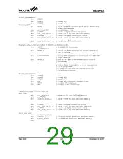
For most applications a resistor connected between
VDD and the RES pin and a capacitor connected be-
tween VSS and the RES pin will provide a suitable ex-
ternal reset circuit. Any wiring connected to the RES
pin should be kept as short as possible to minimise
any stray noise interference.
L
V
R
t
R S T D
S
S
T
T
i
m
e
-
o
u
t
I
n
t
e
r
n
a
l
R
e
s
e
t
Low Voltage Reset Timing Chart
V
R
D
D
1
0
0
k
E
S
m
0 . 1 F
V
S
S
Basic Reset Circuit
For applications that operate within an environment
where more noise is present the Enhanced Reset Cir-
cuit shown is recommended.
Rev. 1.00
33
November 28, 2007

 HOLTEK [ HOLTEK SEMICONDUCTOR INC ]