HT46R4A
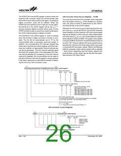
A/D Transfer Function
Interrupt Operation
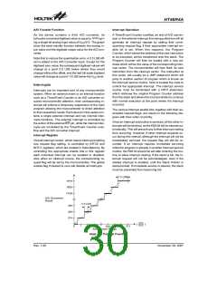
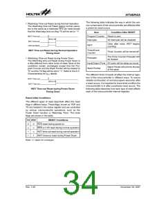
As the device contains a 9-bit A/D converter, its
full-scale converted digitised value is equal to 1FFH giv-
ing a single bit analog input value of VDD/512. The graph
show the ideal transfer function between the analog in-
put value and the digitised output value for the A/D con-
verter.
A Timer/Event Counter overflow, an end of A/D conver-
sion or the external interrupt line being pulled low will all
generate an interrupt request by setting their corre-
sponding request flag, if their appropriate interrupt en-
able bit is set. When this happens, the Program
Counter, which stores the address of the next instruction
to be executed, will be transferred onto the stack. The
Program Counter will then be loaded with a new ad-
dress which will be the value of the corresponding inter-
rupt vector. The microcontroller will then fetch its next
instruction from this interrupt vector. The instruction at
this vector will usually be a JMP statement which will
jump to another section of program which is known as
the interrupt service routine. Here is located the code to
control the appropriate interrupt. The interrupt service
routine must be terminated with a RETI statement,
which retrieves the original Program Counter address
from the stack and allows the microcontroller to continue
with normal execution at the point where the interrupt
occurred.
Note that to reduce the quantisation error, a 0.5 LSB off-
set is added to the A/D Converter input. Except for the
digitised zero value, the subsequent digitised values will
change at a point 0.5 LSB below where they would
change without the offset, and the last full scale digitised
value will change at a point 1.5 LSB below the VDD level.
Interrupts
Interrupts are an important part of any microcontroller
system. When an external event or an internal function
such as a Timer/Event Counter or an A/D converter re-
quires microcontroller attention, their corresponding in-
terrupt will enforce a temporary suspension of the main
program allowing the microcontroller to direct attention
to their respective needs. Each device in this series con-
tains a single external interrupt and two internal inter-
rupts functions. The external interrupt is controlled by
the action of the external INT pin, while the internal inter-
rupts are controlled by the Timer/Event Counter over-
flow and the A/D converter interrupt.
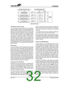
The various interrupt enable bits, together with their as-
sociated request flags, are shown in the following dia-
gram with their order of priority.
Once an interrupt subroutine is serviced, all the other in-
terrupts will be blocked, as the EMI bit will be cleared au-
tomatically. This will prevent any further interrupt nesting
from occurring. However, if other interrupt requests oc-
cur during this interval, although the interrupt will not be
immediately serviced, the request flag will still be re-
corded. If an interrupt requires immediate servicing
while the program is already in another interrupt service
routine, the EMI bit should be set after entering the rou-
tine, to allow interrupt nesting. If the stack is full, the in-
terrupt request will not be acknowledged, even if the
related interrupt is enabled, until the Stack Pointer is
decremented. If immediate service is desired, the stack
must be prevented from becoming full.
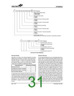
Interrupt Register
Overall interrupt control, which means interrupt enabling
and request flag setting, is controlled by INTC0 and
INTC1 registers, which are located in Data Memory. By
controlling the appropriate enable bits in this register
each individual interrupt can be enabled or disabled.
Also when an interrupt occurs, the corresponding re-
quest flag will be set by the microcontroller. The global
enable flag if cleared to zero will disable all interrupts.
1
.
5
L
S
B
1
F
F
H
1
F
E
H
1
F
D
H
A
R
/
D
C
o
n
v
e
r
s
i
o
n
e
s
u
l
t
0
.
5
L
S
B
0
0
3
2
H
H
0
1
H
V
D
D
(
)
5
1
2
0
1
2
3
5
0
9
5
1
0
5
1
1
5
1
2
A
n
a
l
o
g
I
n
p
u
t
V
o
l
t
a
g
e
Ideal A/D Transfer Function
Rev. 1.00
30
November 28, 2007

 HOLTEK [ HOLTEK SEMICONDUCTOR INC ]