HT46R4A
A
u
t
o
m
a
t
i
c
a
l
l
y
C
l
e
a
r
e
d
b
y
I
S
R
A
u
t
o
m
a
t
i
c
a
l
l
y
D
i
s
a
b
l
e
d
b
y
I
S
R
M
a
n
u
a
l
l
y
S
e
t
o
r
C
l
e
a
r
e
d
b
y
S
o
f
t
w
a
r
e
C
a
n
b
e
E
n
a
b
l
e
d
M
a
n
u
a
l
l
y
P
r
i
o
r
i
t
y
E
x
e
t
e
r
n
a
l
I
n
t
e
r
r
u
p
t
E
E
I
E
M
I
H
i
g
h
R
q
u
e
s
t
F
l
a
g
E
I
F
T
i
m
e
r
/
E
v
e
n
t
C
o
u
n
t
e
r
0
E
E
E
T
T
A
0
1
I
I
I
n
t
e
r
r
u
p
t
R
e
q
u
e
s
t
F
l
a
g
T
0
F
I
n
t
e
r
r
u
p
t
P
o
l
l
i
n
g
T
i
m
e
r
/
E
v
e
n
t
C
o
u
n
t
e
r
1
I
n
t
e
r
r
u
p
t
R
e
q
u
e
s
t
F
l
a
g
T
1
F
A
/
D
C
o
n
v
e
r
t
e
r
D
I
L
o
w
I
n
t
e
r
r
u
p
t
R
e
q
u
e
s
t
F
l
a
g
A
D
F
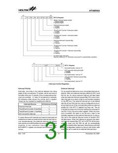
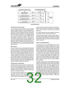
Interrupt Structure
Timer/Event Counter Interrupt
only one stack is left and the interrupt is not well con-
trolled, the original control sequence will be damaged
once a ²CALL subroutine² is executed in the interrupt
subroutine.
For a Timer/Event Counter interrupt to occur, the global
interrupt enable bit, EMI, and the corresponding timer
interrupt enable bit, ET0I/ET1I; bit 2/bit 3 of INTC0 must
first be set. An actual Timer/Event Counter interrupt will
take place when the Timer/Event Counter request flag,
T0F/T1F; bit 5/bit 6 of INTC0 is set, a situation that will
occur when the Timer/Event Counter overflows. When
the interrupt is enabled, the stack is not full and a
Timer/Event Counter overflow occurs, a subroutine call
to the timer interrupt vector at location 08H/0CH, will
take place. When the interrupt is serviced, the timer in-
terrupt request flag, T0F/T1F, will be automatically reset
and the EMI bit will be automatically cleared to disable
other interrupts.
All of these interrupts have the capability of waking up
the processor when in the Power Down Mode.
Only the Program Counter is pushed onto the stack. If
the contents of the register or status register are altered
by the interrupt service program, which may corrupt the
desired control sequence, then the contents should be
saved in advance.
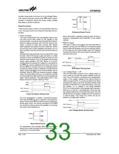
Reset and Initialisation
A reset function is a fundamental part of any
microcontroller ensuring that the device can be set to
some predetermined condition irrespective of outside
parameters. The most important reset condition is after
power is first applied to the microcontroller. In this case,
internal circuitry will ensure that the microcontroller, af-
ter a short delay, will be in a well defined state and ready
to execute the first program instruction. After this
power-on reset, certain important internal registers will
be set to defined states before the program com-
mences. One of these registers is the Program Counter,
which will be reset to zero forcing the microcontroller to
begin program execution from the lowest Program
Memory address.
A/D Interrupt
For an A/D interrupt to occur, the global interrupt enable
bit, EMI, and the corresponding interrupt enable bit,
EADI, must be first set. An actual A/D interrupt will take
place when the A/D converter request flag, ADF; bit 4 of
INTC1 is set, a situation that will occur when an A/D con-
version process has completed. When the interrupt is
enabled, the stack is not full and an A/D conversion pro-
cess finishes execution, a subroutine call to the A/D in-
terrupt vector at location 10H, will take place. When the
interrupt is serviced, the A/D interrupt request flag, ADF,
will be automatically reset and the EMI bit will be auto-
matically cleared to disable other interrupts.
In addition to the power-on reset, situations may arise
where it is necessary to forcefully apply a reset condition
when the microcontroller is running. One example of this
is where after power has been applied and the
microcontroller is already running, the RES line is force-
fully pulled low. In such a case, known as a normal oper-
ation reset, some of the microcontroller registers remain
unchanged allowing the microcontroller to proceed with
normal operation after the reset line is allowed to return
high. Another type of reset is when the Watchdog Timer
overflows and resets the microcontroller. All types of re-
set operations result in different register conditions be-
ing setup.
Programming Considerations
By disabling the interrupt enable bits, a requested inter-
rupt can be prevented from being serviced, however,
once an interrupt request flag is set, it will remain in this
condition in the INTC0/INTC1 register until the corre-
sponding interrupt is serviced or until the request flag is
cleared by a software instruction.
It is recommended that programs do not use the ²CALL
subroutine² instruction within the interrupt subroutine.
Interrupts often occur in an unpredictable manner or
need to be serviced immediately in some applications. If
Rev. 1.00
32
November 28, 2007

 HOLTEK [ HOLTEK SEMICONDUCTOR INC ]