HT46R4A
Oscillator
Various oscillator options offer the user a wide range of
functions according to their various application require-
ments. Two types of system clocks can be selected
while various clock source options for the Watchdog
Timer are provided for maximum flexibility. All oscillator
options are selected through the configuration options.
Table: capacitor selection for system crystal/ceramic
oscillator.
C1, C2 Value
Crystal Frequency
8MHz
C1
C2
CL*
TBD
TBD
TBD
TBD
TBD
TBD
TBD
TBD
TBD
TBD
TBD
TBD
More information regarding the oscillator is located in
Application Note HA0075E on the Holtek website.
4MHz
1MHz
Clock Source Modes
400kHz
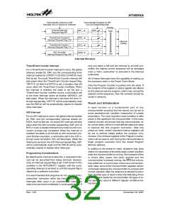
There are two methods of generating the system clock,
using an external crystal/ceramic oscillator and an ex-
ternal RC network. One of these two methods must be
selected using the configuration options.
Note: 1. The C1, C2 value is for design guidance
only and not optimized. Due to the different
performance of various crystals/resonators,
it¢s suggested to test it over expected VDD
and temperature for the application, and
consult the manufacturer for appropriate val-
ues of external components.
·
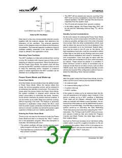
External Crystal/Ceramic Oscillator
The simple connection of a crystal across OSC1 and
OSC2 will create the necessary phase shift and feed-
back for oscillation, without requiring external capaci-
tors. However, for some crystal types and
frequencies, to ensure oscillation, it may be neces-
sary to add two small value capacitors, C1 and C2.
Using a ceramic resonator will usually require two
small value capacitors, C1 and C2, to be connected
as shown for oscillation to occur. The values of C1 and
C2 should be selected in consultation with the crystal
or resonator manufacturer¢s specification.
2. ²CL*² is the load capacitor for tested crys-
tal which is specified in crystal specification.
Table: Build-in RC value for system crystal/ceramic
oscillator.
Ca, Cb, Rf Value (5V, 25° C)
Ca
Cb
Rf
TBD
TBD
TBD
H
o
l
t
e
k
M
C
U
C
1
O
S
C
1
C
a
·
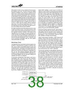
External RC Oscillator
R
p
R
f
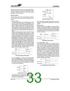
Using the external RC network as an oscillator requires
that a resistor, with a value between 24kW and 1MW, is
connected between OSC1 and ground, and a 470pF
capacitor is connected to VDD. The generated system
clock divided by 4 will be provided on OSC2 as an out-
put which can be used for external synchronization pur-
poses. Note that as the OSC2 output is an NMOS
open-drain type, a pull high resistor should be con-
nected if it to be used to monitor the internal frequency.
Although this is a cost effective oscillator configuration,
the oscillation frequency can vary with VDD, tempera-
ture and process variations on the device itself and is
therefore not suitable for applications where timing is
critical or where accurate oscillator frequencies are re-
quired. For the value of the external resistor ROSC
please refer to the Appendix section for typical RC Os-
cillator vs. Temperature and VDD characteristics graph-
ics.
C
b
T
o
i
n
t
e
r
n
a
l
c
i
r
c
u
i
t
O
S
C
2
C
2
N
o
t
e
:
U
i
s
u
a
l
l
y
,
a
n
a
d
d
i
t
i
o
n
a
l
p
a
r
a
l
l
e
l
f
e
e
d
b
a
c
k
r
e
s
i
s
t
o
r
(
R
p
)
s
n
o
t
n
e
c
e
s
s
a
r
y
(
I
t
m
a
y
b
e
r
e
q
u
i
r
e
d
t
o
a
s
s
i
s
t
o
s
c
i
l
l
a
t
i
o
n
s
t
a
r
t
-
u
p
)
.
External Crystal/Ceramic Oscillator
Rev. 1.00
36
November 28, 2007

 HOLTEK [ HOLTEK SEMICONDUCTOR INC ]