HT46R4A
·
The WDT will be cleared and resume counting if the
WDT clock source is selected to come from the WDT
internal oscillator. The WDT will stop if its clock source
originates from the system clock.
V
D
D
4
7
0
p
F
O
S
C
1
·
·
The I/O ports will maintain their present condition.
R
O
S
C
In the status register, the Power Down flag, PDF, will
be set and the Watchdog time-out flag, TO, will be
cleared.
f
S
Y
S
/
4
N
M
O
S
O
p
e
n
D
r
a
i
n
O
S
C
2
Standby Current Considerations
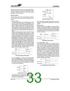
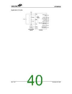
External RC Oscillator
As the main reason for entering the Power Down Mode
is to keep the current consumption of the MCU to as low
a value as possible, perhaps only in the order of several
micro-amps, there are other considerations which must
also be taken into account by the circuit designer if the
power consumption is to be minimised. Special atten-
tion must be made to the I/O pins on the device. All
high-impedance input pins must be connected to either
a fixed high or low level as any floating input pins could
create internal oscillations and result in increased cur-
rent consumption. Care must also be taken with the
loads, which are connected to I/O pins, which are setup
as outputs. These should be placed in a condition in
which minimum current is drawn or connected only to
external circuits that do not draw current, such as other
CMOS inputs. Also note that additional standby current
will also be required if the configuration options have en-
abled the Watchdog Timer internal oscillator.
Note that it is the only microcontroller internal circuitry
together with the external resistor, that determine the
frequency of the oscillator. The external capacitor
shown on the diagram does not influence the frequency
of oscillation. The external capacitor is added to improve
oscillator stability, especially if the open-drain OSC2
output is utilised in the application circuit.
Watchdog Timer Oscillator
The WDT oscillator is a fully self-contained free running
on-chip RC oscillator with a typical period of 65ms at 5V
requiring no external components. When the device en-
ters the Power Down Mode, the system clock will stop
running but the WDT oscillator continues to free-run and
to keep the watchdog active. However, to preserve
power in certain applications the WDT oscillator can be
disabled via a configuration option.
Wake-up
Power Down Mode and Wake-up
After the system enters the Power Down Mode, it can be
woken up from one of various sources listed as follows:
Power Down Mode
·
All of the Holtek microcontrollers have the ability to enter
a Power Down Mode. When the device enters this
mode, the normal operating current, will be reduced to
an extremely low standby current level. This occurs be-
cause when the device enters the Power Down Mode,
the system oscillator is stopped which reduces the
power consumption to extremely low levels, however,
as the device maintains its present internal condition, it
can be woken up at a later stage and continue running,
without requiring a full reset. This feature is extremely
important in application areas where the MCU must
have its power supply constantly maintained to keep the
device in a known condition but where the power supply
capacity is limited such as in battery applications.
An external reset
·
·
·
An external falling edge on Port A
A system interrupt
A WDT overflow
If the system is woken up by an external reset, the de-
vice will experience a full system reset, however, if the
device is woken up by a WDT overflow, a Watchdog
Timer reset will be initiated. Although both of these
wake-up methods will initiate a reset operation, the ac-
tual source of the wake-up can be determined by exam-
ining the TO and PDF flags. The PDF flag is cleared by a
system power-up or executing the clear Watchdog
Timer instructions and is set when executing the ²HALT²
instruction. The TO flag is set if a WDT time-out occurs,
and causes a wake-up that only resets the Program
Counter and Stack Pointer, the other flags remain in
their original status.
Entering the Power Down Mode
There is only one way for the device to enter the Power
Down Mode and that is to execute the ²HALT² instruc-
tion in the application program. When this instruction is
executed, the following will occur:
Each pin on Port A can be setup via an individual config-
uration option to permit a negative transition on the pin
·
The system oscillator will stop running and the appli-
to wake-up the system. When a Port A pin wake-up oc-
curs, the program will resume execution at the instruc-
tion following the ²HALT² instruction.
cation program will stop at the ²HALT² instruction.
·
The Data Memory contents and registers will maintain
their present condition.
Rev. 1.00
37
November 28, 2007

 HOLTEK [ HOLTEK SEMICONDUCTOR INC ]