HT46R4A
b
7
b
0
T
1
F
T
0
F
E
I
F
E
T
1
I
E
T
0
I
E
E
I
E
M
I
I
N
T
C
0
R
e
g
i
s
t
e
r
M
a
s
t
o
e
r
i
n
t
e
r
r
u
p
t
g
l
o
b
a
l
e
n
a
b
l
e
1
0
:
:
g
l
b
a
l
e
e
e
e
n
a
b
l
e
g
l
o
b
a
l
d
i
s
a
b
l
e
E
1
0
x
t
t
r
e
r
n
a
l
i
n
t
e
r
r
u
p
t
e
n
a
b
l
e
:
:
e
d
n
i
a
b
b
b
l
l
l
s
a
a
a
b
l
v
l
v
l
e
e
e
T
1
0
i
m
e
n
i
r
a
/
E
e
n
t
C
o
u
n
t
e
r
0
i
n
t
e
r
r
u
u
l
u
u
p
t
e
n
a
b
l
e
:
:
e
d
s
b
T
1
0
i
m
e
n
i
r
a
/
E
e
n
t
C
o
u
n
t
e
r
1
i
n
t
e
r
r
p
t
e
n
a
b
l
e
:
:
e
d
s
b
E
1
0
x
e
r
n
a
l
i
n
t
e
r
r
u
p
t
0
r
e
q
u
e
s
t
f
a
g
:
:
a
i
c
t
i
c
v
e
n
a
t
i
v
e
T
i
m
e
c
r
/
E
v
e
n
t
C
o
u
n
t
e
r
0
i
n
t
e
r
r
p
t
e
n
a
b
l
e
1
0
:
:
a
i
t
i
c
v
e
n
a
t
i
v
e
T
1
0
i
m
e
c
r
/
E
v
e
n
t
C
o
u
n
t
e
r
1
i
n
t
e
r
r
p
t
r
e
q
u
e
s
t
f
l
a
g
:
:
a
i
t
i
c
v
e
n
a
t
i
v
e
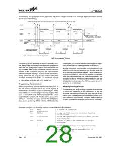
F
M
o
t
e
s
t
m
o
d
e
u
s
e
d
o
n
l
y
u
s
t
b
e
w
r
i
t
t
e
n
a
s
"
0
"
;
o
t
h
e
r
w
i
s
e
m
a
y
r
e
s
u
l
t
i
n
u
n
p
r
e
d
i
c
t
a
b
l
e
o
p
e
r
a
t
i
o
n
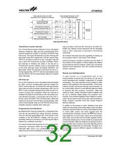
b
7
b
0
A
D
F
E
A
D
I
I
N
T
C
1
R
e
g
i
s
t
e
r
N
o
t
i
m
p
l
e
m
e
n
t
e
d
,
r
e
a
d
a
s
"
0
"
A
/
D
C
o
n
v
e
r
t
e
r
i
n
t
e
r
r
u
p
t
e
n
a
b
l
e
1
0
:
:
e
d
n
i
a
b
l
e
s
a
b
l
e
N
o
t
i
m
p
l
e
m
e
n
t
e
d
,
r
e
a
d
a
s
"
0
"
A
1
0
/
D
c
o
i
c
n
v
e
r
t
e
r
i
n
t
e
r
r
u
p
t
r
e
q
u
e
s
t
f
l
a
g
:
:
a
i
c
t
v
e
n
a
t
i
v
l
e
N
o
t
i
m
p
e
m
e
n
t
e
d
,
r
e
a
d
a
s
"
0
"
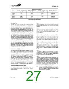
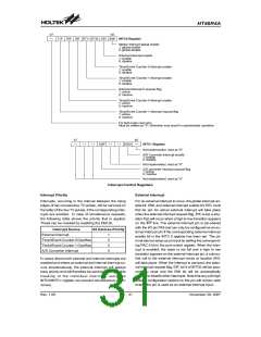
Interrupt Control Registers
Interrupt Priority
External Interrupt
Interrupts, occurring in the interval between the rising
edges of two consecutive T2 pulses, will be serviced on
the latter of the two T2 pulses, if the corresponding inter-
rupts are enabled. In case of simultaneous requests,
the following table shows the priority that is applied.
These can be masked by resetting the EMI bit.
For an external interrupt to occur, the global interrupt en-
able bit, EMI, and external interrupt enable bit, EEI, must
first be set. An actual external interrupt will take place
when the external interrupt request flag, EIF, is set, a situ-
ation that will occur when a high to low transition appears
on the INT line. The external interrupt pin is pin-shared
with the I/O pin PA5 and can only be configured as an ex-
ternal interrupt pin if the corresponding external interrupt
enable bit in the INTC 0 register has been set. The pin
must also be setup as an input by setting the correspond-
ing PAC.5 bit in the port control register. When the inter-
rupt is enabled, the stack is not full and a high to low
transition appears on the external interrupt pin, a subrou-
tine call to the external interrupt vector at location 04H,
will take place. When the interrupt is serviced, the exter-
nal interrupt request flag, EIF; bit 4 of INTC0 will be auto-
matically reset and the EMI bit will be automatically
cleared to disable other interrupts. Note that any pull-high
resistor configuration options on this pin will remain valid
even if the pin is used as an external interrupt input.
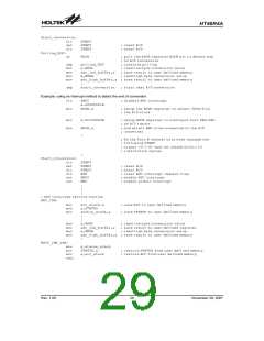
Interrupt Source
External Interrupt
All Devices Priority
1
2
3
4
Timer/Event Counter 0 Overflow
Timer/Event Counter 1 Overflow
A/D Converter Interrupt
In cases where both external and internal interrupts are
enabled and where an external and internal interrupt oc-
curs simultaneously, the external interrupt will always
have priority and will therefore be serviced first. Suitable
masking of the individual interrupts using the
INTC0/INTC1 register can prevent simultaneous occur-
rences.
Rev. 1.00
31
November 28, 2007

 HOLTEK [ HOLTEK SEMICONDUCTOR INC ]