HT48RA0-3/HT48CA0-3
·
·
If the TSR1.1 is cleared during the timer counting, the
timer will be stopped. Once the TSR1.1 is set
(1®0®1), the down counter will reload data from
t8~t0, and then the down counter begins counting
down with the new load data.
In the case above, the timer output time is as follows.
(Set value+1) ´ 64/fSYS
= (511+1) ´ 16ms
= 8.192ms
If TSR1.1 and TOEF are equal to 1 both, the timer can
re-start, after new data is written to TSR0, TSR1
(t0~t8) in sequence.
R
E
M
Note: If the contents of the Down counter is 000H, set
the t9 to start the timer counting, the timer will
8
.
1
9
2
m
s
only count
1 step. The timer output
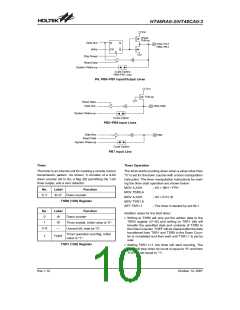
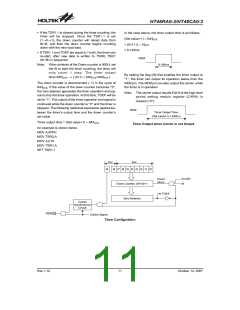
By setting the flag (t9) that enables the timer output to
²1², the timer can output its operation status from the
REM pin. The REM pin can also output the carrier while
the timer is in operation.
time=64/fSYS. ® [ (0+1) ´ 64/fSYS=64/fSYS
]
The down counter is decremented (-1) in the cycle of
64/fSYS. If the value of the down counter becomes ²0²,
the zero detector generates the timer operation end sig-
nal to stop the timer operation. At this time, TOEF will be
set to ²1². The output of the timer operation end signal is
continued while the down counter is ²0² and the timer is
stopped. The following relational expression applies be-
tween the timer¢s output time and the down counter¢s
set value.
Note: The carrier output results if bit 9 of the high-level
period setting modulo register (CARH) is
cleared (²0²).
R
E
M
T
i
m
e
r
O
u
t
p
u
t
T
i
m
e
:
(
S
e
t
v
a
l
u
e
+
1
)
x
6
4
/
f
Timer output time = (Set value+1) ´ 64/fSYS
Timer Output when Carrier is not Output
An example is shown below.
MOV A,0FFH
MOV TSR0,A
MOV A,01H
MOV TSR1,A
SET TSR1.1
t
S
R
1
t
S R 0
t
9
t
8
t
7
t
6
t
5
t
4
t
3
t
2
t
1
t
0
f
t
S
Y
S
C
o
u
n
t
C
l
o
c
k
D
o
w
n
C
o
u
n
t
e
r
,
(
t
8
~
t
0
)
+
1
9
T
O
E
F
Z
e
r
o
D
e
t
e
c
t
o
r
C
a
r
r
i
e
r
S
y
n
c
h
r
o
n
o
u
s
C
i
r
c
u
i
t
R
E
M
C
a
r
r
i
e
r
S
i
g
n
a
l
Timer Configuration
Rev.1.10
11
October 12, 2007

 HOLTEK [ HOLTEK SEMICONDUCTOR INC ]