HT48RA0-3/HT48CA0-3
V
D
D
W
e
a
k
P
u
l
l
-
u
p
D
a
t
a
b
u
s
D
C
Q
P
A
0
~
P
A
7
P
B
0
~
P
B
1
W
r
i
t
e
K
Q
S
C
h
i
p
R
e
s
e
t
R
e
a
d
D
a
t
a
p
S
y
s
t
e
m
W
a
k
e
-
u
C
o
d
e
O
p
t
i
o
n
P
B
0
~
P
B
1
o
n
l
y
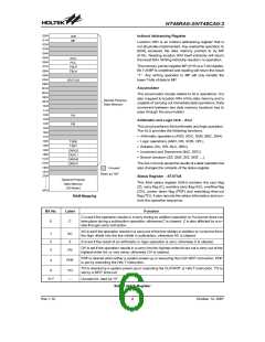
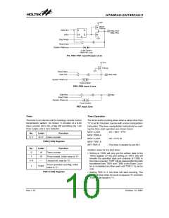
PA, PB0~PB1 Input/Output Lines
V
D
D
P
u
l
l
-
u
p
R
e
a
d
D
a
t
a
D
a
t
a
b
u
s
P
B
2
~
P
B
6
S
y
s
t
e
m
W
a
k
e
-
u
p
C
o
d
e
O
p
t
i
o
n
PB2~PB6 Input Lines
D
a
t
a
B
u
s
P
B
7
R
e
a
d
D
a
t
a
S
y
s
t
e
m
W
a
k
e
-
u
p
C
o
d
e
O
p
t
i
o
n
PB7 Input Line
Timer
Timer Operation
The timer is an internal unit for creating a remote control
transmission pattern. As shown, it consists of a 9-bit
down counter (t8 to t0), a flag (t9) permitting the 1-bit
timer output, and a zero detector.
The timer starts counting down when a value other than
²0² is set for the down counter with a timer manipulation
instruction. The timer manipulation instructions for mak-
ing the timer start operation are shown below:
MOV A,XXH
MOV TSR0,A
MOV A,XXH
MOV TSR1,A
SET TSR1.1
; XX = 00H ~ FFH
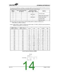
No.
Label
Function
0~7
t0~t7 Down counter
; XX £ 01H, t8
TSR0 (18H) Register
; The timer is started by set t9=1
No.
0
Label
t8
Function
Addition notes for the 9-bit timer:
Down counter
·
Writing to TSR0 will only put the written data to the
TSR0 register (t7~t0) and writing to TSR1 (t8) will
transfer the specified data and contents of TSR0 to
the Down Counter. TOEF will be cleared after the data
transferred from TSR1 and TSR0 to the Down Coun-
ter is completed and then wait until TSR1.1 is set by
user.
1
t9
Timer enable, initial value is ²0².
Unused bit, read as ²0².
2~6
¾
Timer operation end flag, initial
7
TOEF
value is ²1².
TSR1 (19H) Register
·
Setting TSR1.1=1, the timer will start counting. The
timer will stop when its count is equal to ²0² and then
TOEF is set equal to ²1².
Rev.1.10
10
October 12, 2007

 HOLTEK [ HOLTEK SEMICONDUCTOR INC ]