HT48RA0-3/HT48CA0-3
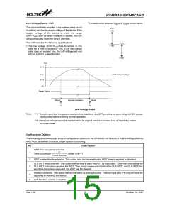
Low Voltage Reset - LVR
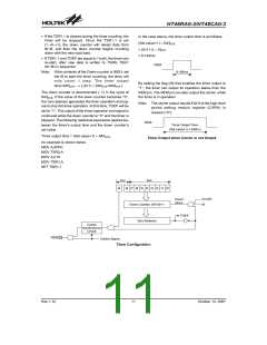
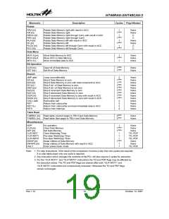
The relationship between VDD and VLVR is shown below.
The microcontroller provides a low voltage reset circuit
in order to monitor the supply voltage of the device. If the
supply voltage of the device is within the range
0.9V~VLVR, such as when changing a battery, the LVR
will automatically reset the device internally.
V
D
D
3
.
6
V
The LVR includes the following specifications:
V
L
V
R
1
.
9
V
·
The low voltage (0.9V~VLVR) has to remain in this
state for a time in excess of 1ms. If the low voltage
state does not exceed 1ms, the LVR will ignore it and
will not perform a reset function.
0
.
9
V
V
D
D
3
.
6
V
L
V
R
D
e
t
e
c
t
V
o
l
t
a
g
e
V
L
V
R
0
.
9
0
V
V
R
e
s
e
t
S
i
g
n
a
l
R
e
s
e
t
N
o
r
m
a
l
O
p
e
r
a
t
i
o
n
R
e
s
e
t
*
1
*
2
Low Voltage Reset
Note:
²*1² To make sure that the system oscillator has stabilised, the SST provides an extra delay of 1024 system
clock pulses before entering normal operation.
²*2² Since low voltage has to be maintained in its original state and exceed 1ms, a 1ms delay enters
the reset mode.
Configuration Options
The following table shows eight kinds of configuration options for the HT48RA0-3/HT48CA0-3. All the configuration op-
tions must be defined to ensure proper system functioning.
No.
1
Code Option
WDT time-out period selection
2n
Time-out period=
, where n=8~11.
Clock Source
2
WDT enable/disable selection. This option is to decide whether the WDT timer is enabled or disabled.
CLR WDT times selection. This option defines how to clear the WDT by instruction. ²One time² means that the
CLR WDT instruction can clear the WDT. ²Two times² means only if both of the CLR WDT1 and CLR WDT2 in-
structions have been executed, the WDT can be cleared.
3
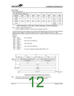
Wake-up selection. This option defines the wake-up activity function. External input pins (PB only) all have the
capability to wake-up the device.
4
5
LVR function: enable or disable
Rev.1.10
15
October 12, 2007

 HOLTEK [ HOLTEK SEMICONDUCTOR INC ]