19.2
Flash Memory Register Descriptions
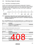
19.2.1 Flash Memory Control Register (FLMCR)
FLMCR is an 8-bit register that controls the flash memory operating modes. Transitions to
program mode, erase mode, program-verify mode, and erase-verify mode are made by setting bits
in this register. FLMCR is initialized to H'00 by a reset, in the standby modes, and when 12 V is
not applied to FVPP. When 12 V is applied to the FVPP pin, a reset or entry to a standby mode
initializes FLMCR to H'80.
Bit
7
VPP
0
6
—
0
5
—
0
4
—
0
3
EV
0
2
PV
0
1
E
0
P
Initial value*
0
0
Read/Write
R
—
—
—
R/W*
R/W*
R/W*
R/W*
Note: * The initial value is H'00 in modes 2 and 3 (on-chip flash memory enabled). In mode 1 (on-
chip flash memory disabled), this register cannot be modified and always reads H'FF. For
information on accessing this register, refer to in section 19.7, Flash Memory Programming
and Erasing Precautions (11).
Bit 7—Programming Power (VPP): This status flag indicates that 12 V is applied to the FVPP pin.
Refer to section 19.7, Flash Memory Programming and Erasing Precautions (5), for details on use.
Bit 7: VPP
Description
0
1
Cleared when 12 V is not applied to FVPP
Set when 12 V is applied to FVPP
(Initial value)
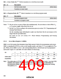
Bits 6 to 4—Reserved: Read-only bits, always read as 0.
Bit 3—Erase-Verify Mode (EV):*1 Selects transition to or exit from erase-verify mode.
Bit 3: EV
Description
0
1
Exit from erase-verify mode
Transition to erase-verify mode
(Initial value)
Bit 2—Program-Verify Mode (PV):*1 Selects transition to or exit from program-verify mode.
Bit 2: PV
Description
0
1
Exit from program-verify mode
Transition to program-verify mode
(Initial value)
379

 HITACHI [ HITACHI SEMICONDUCTOR ]