Pin
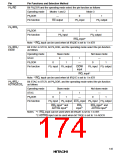
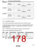
Pin Functions and Selection Method
PA2/KEYIN10
PA2DDR
0
1
Pin function
PA2 input
PA2 output
KEYIN10 input
KEYIN9 input
KEYIN8 input
PA1/KEYIN9
PA0/KEYIN8
PA1DDR
0
1
Pin function
PA1 input
PA1 output
PA0DDR
0
1
Pin function
PA0 input
PA0 output
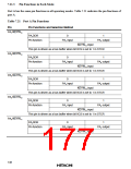
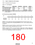
7.11.4 Input Pull-Up Transistors
Port A has built-in programmable input pull-up transistors that are available in all modes.
An input pull-up transistor is turned on if 1 is written in the corresponding PAODR bit while the
corresponding PADDR bit is cleared to 0. The input pull-ups are turned off by a reset and in
hardware standby mode.
Table 7.22 indicates the states of the input pull-up transistors in each operating mode.
Table 7.22 States of Input Pull-Up Transistors (Port A)
Mode
Reset
Off
Hardware Standby
Software Standby
On/off
Other Operating Modes
1
2
3
Off
Off
Off
On/off
On/off
On/off
Off
On/off
Off
On/off
Notes: Off:
The input pull-up transistor is always off.
On/off: The input pull-up transistor is on if PAODR = 1 and PADDR = 0, but off otherwise.
149

 HITACHI [ HITACHI SEMICONDUCTOR ]