4.11.4 Parallel Output in Data-Through Mode
When operating in Data-Through mode, (see Data Through Mode on page 39), the
GS1559 presents data to the output data bus without performing any decoding,
descrambling or word-alignment.
As described in Data Through Mode on page 39, the data bus outputs will be forced to
logic LOW if the device is set to operate in Master mode but cannot identify SMPTE TRS
ID in the input data stream.
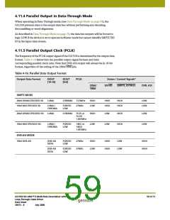
4.11.5 Parallel Output Clock (PCLK)
The frequency of the PCLK output signal of the GS1559 is determined by the output data
format. Table 4-16 below lists the possible output signal formats and their
corresponding parallel clock rates. Note that DVB-ASI output will always be in 10-bit
format, regardless of the setting of the 20bit/10bit pin.
Table 4-16: Parallel Data Output Format
Output Data Format
DOUT
[19:10]
DOUT
[9:0]
PCLK
Status / Control Signals*
20bit/
10bit
SD/HD
SMPTE_BYPASS
DVB_ASI
SMPTE MODE
20bit DEMULTIPLEXED SD
10bit MULTIPLEXED SD
LUMA
CHROMA
13.5MHz
27MHz
HIGH
LOW
HIGH
HIGH
HIGH
HIGH
LOW
LOW
LUMA /
CHROMA
FORCED
LOW
20bit DEMULTIPLEXED HD
10bit MULTIPLEXED HD
LUMA
CHROMA
74.25 or
74.25/
1.001MHz
HIGH
LOW
LOW
LOW
HIGH
HIGH
LOW
LOW
LUMA /
CHROMA
FORCED
LOW
148.5 or
148.5/
1.001MHz
DVB-ASI MODE
10bit DVB-ASI
DVB-ASI
DATA
FORCED
LOW
27MHz
27MHz
HIGH
LOW
HIGH
HIGH
LOW
LOW
HIGH
HIGH
DVB-ASI
DATA
FORCED
LOW
GS1559 HD-LINX™ II Multi-Rate Deserializer with
Loop-Through Cable Driver
Data Sheet
59 of 71
30572 - 8
July 2008

 GENNUM [ GENNUM CORPORATION ]