4.13 JTAG
When the JTAG/HOST input pin of the GS1559 is set HIGH, the Host Interface port will
be configured for JTAG test operation. In this mode, pins H4 to H6 and J6 become TMS,
TCK, TDO, and TDI. In addition, the RESET_TRST pin will operate as the test reset pin.
Boundary scan testing using the JTAG interface will be enabled in this mode.
There are two methods in which JTAG can be used on the GS1559:
1. As a stand-alone JTAG interface to be used at in-circuit ATE (Automatic Test
Equipment) during PCB assembly; or
2. Under control of the host for applications such as system power on self tests.
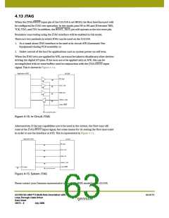
When the JTAG tests are applied by ATE, care must be taken to disable any other devices
driving the digital I/O pins. If the tests are to be applied only at ATE, this can be
accomplished with tri-state buffers used in conjunction with the JTAG/HOST input
signal. This is shown in Figure 4-14.
Application HOST
GS1559
CS_TMS
SCLK_TCK
SDIN_TDI
SDOUT_TDO
JTAG_HOST
In-circuit ATE probe
Figure 4-14: In-Circuit JTAG
Alternatively, if the test capabilities are to be used in the system, the Host may still
control the JTAG/HOST input signal, but some means for tri-stating the Host must exist
in order to use the interface at ATE. This is represented in Figure 4-15.
Application HOST
GS1559
CS_TMS
SCLK_TCK
SDIN_TDI
SDOUT_TDO
JTAG_HOST
Tri-State
In-circuit ATE probe
Figure 4-15: System JTAG
Please contact your Gennum representative to obtain the BSDL model for the GS1559.
GS1559 HD-LINX™ II Multi-Rate Deserializer with
Loop-Through Cable Driver
Data Sheet
63 of 71
30572 - 8
July 2008

 GENNUM [ GENNUM CORPORATION ]