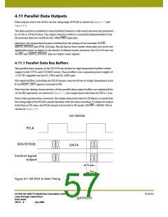
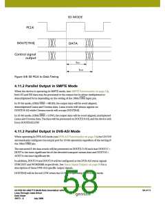
SD MODE
PCLK
DOUT[19:0]
DATA
Control signal
output
tOH
tOD
Figure 4-8: SD PCLK to Data Timing
4.11.2 Parallel Output in SMPTE Mode
When the device is operating in SMPTE mode, (see SMPTE Functionality on page 31),
both SD and HD data may be presented to the output bus in either multiplexed or
demultiplexed form depending on the setting of the 20bit/10bit input pin.
In 20-bit mode, (20bit/10bit = HIGH), the output data will be word aligned,
demultiplexed Luma and Chroma data. Luma words will always appear on
DOUT[19:10] while Chroma words will occupy DOUT[9:0].
In 10-bit mode, (20bit/10bit = LOW), the output data will be word aligned, multiplexed
Luma and Chroma data. The data will be presented on DOUT[19:10], and the device will
force DOUT[9:0] LOW.
4.11.3 Parallel Output in DVB-ASI Mode
When operating in DVB-ASI mode, (see DVB-ASI Functionality on page 38), the GS1559
automatically configures the output port for 10-bit operation regardless of the setting of
the 20bit/10bit pin.
The extracted 8-bit data words will be presented on DOUT[17:10] such that DOUT17 =
HOUT is the most significant bit of the decoded transport stream data and DOUT10 =
AOUT is the least significant bit.
In addition, DOUT19 and DOUT18 will be configured as the DVB-ASI status signals
SYNCOUT and WORDERR respectively. See Status Signal Outputs on page 38 for a
description of these DVB-ASI specific output signals.
DOUT[9:0] will be forced LOW when the GS1559 is operating in DVB-ASI mode.
GS1559 HD-LINX™ II Multi-Rate Deserializer with
Loop-Through Cable Driver
Data Sheet
58 of 71
30572 - 8
July 2008

 GENNUM [ GENNUM CORPORATION ]