FT2232C Dual USB UART / FIFO I.C.
Alternatively, a dedicated power switch I.C. with inbuilt “soft-start” can be used instead of a MOSFET. A suitable
power switch I.C. for such an application would be a Micrel (www.micrel.com) MIC2025-2BM or equivalent.
Please note the following points in connection with power controlled designs –
a) The logic to be controlled must have its own reset circuitry so that it will automatically reset itself when power is re-
applied on coming out of suspend.
b) Set the Pull-down on Suspend option in the FT2232C’s EEPROM.
c) For USB high-power bus powered device (one that consumes greater than 100 mA, and up to 500 mA of current
from the USB bus), the power consumption of the device should be set in the max power field in the EEPROM.
A high-power bus powered device must use this descriptor in the EEPROM to inform the system of its power
requirements.
d) For 3.3V power controlled circuits the VCCIO pins must not be powered down with the external circuitry. Either
connect the power switch between the output of the 3.3V regulator and the external 3.3V logic, or if appropriate
power the VCCIO pin from the 3V3OUT pin of the FT2232C.
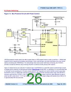
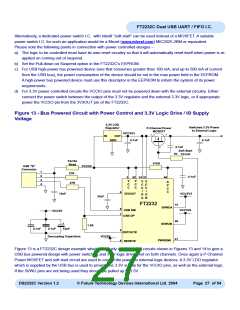
Figure 13 - Bus Powered Circuit with Power Control and 3.3V Logic Drive / IO Supply
Voltage
3.3V LDO
Regulator
Switched 3.3V Power
to External Logic
P-Channel Power
MOSFET
VCC3V3
s
d
IN
OUT
GND
0.1uF
0.1uF
g
0.1uF
Soft Start
1K
Circuit
Ferrite
Bead
470R
USB "B"
VCC5V
Connector
1
2
3
4
27R
27R
0.1uF
3
V
C
C
42 14 31
46
V
C
C
V
C
C
I
V
C
C
I
A
V
C
C
6
10nF
3V3OUT
VCC3V3
VCC3V3
O
A
O
B
33nF
FT2232
10
26
SI/WUA
SI/WUB
8
7
USB DM
USB DP
VCC5V
+
1.5K
0.1uF
0.1uF
10uF
5
4
RSTOUT#
RESET#
Decoupling Capacitors
VCC5V
41
PWREN#
Figure 13 is a FT2232C design example which effectively combines the circuits shown in Figures 13 and 14 to give a
USB bus powered design with power switching and 3.3V logic drive level on both channels. Once again a P-Channel
Power MOSFET and soft start circuit are used to control the power to external logic devices. A 3.3V LDO regulator
which is supplied by the USB bus is used to provide the 3.3V supply for the VCCIO pins, as well as the external logic.
If the SI/WU pins are not being used they should be pulled up to 3.3V.
DS2232C Version 1.2
© Future Technology Devices International Ltd. 2004
Page 27 of 54

 FTDI [ FUTURE TECHNOLOGY DEVICES INTERNATIONAL LTD. ]