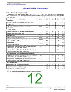
ELECTRICAL CHARACTERISTICS
STATIC ELECTRICAL CHARACTERISTICS
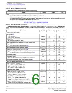
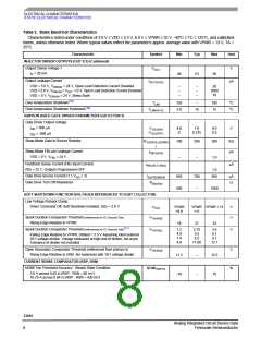
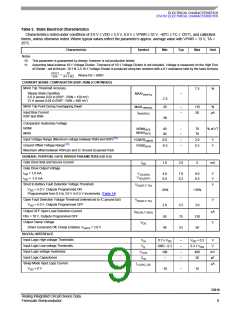
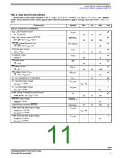
Table 3. Static Electrical Characteristics
Characteristics noted under conditions of 3.0 V ≤ VDD ≤ 5.5 V, 6.0 V ≤ VPWR ≤ 32 V, -40°C ≤ TC ≤ 125°C, and calibrated
timers, unless otherwise noted. Where typical values reflect the parameter’s approx. average value with VPWR = 13 V, TA =
25°C.
Characteristic
Symbol
Min
Typ
Max
Unit
INJECTOR DRIVER OUTPUTS (OUT 0:3) (Continued)
Output Clamp Voltage 1
V
V
OC1
I
= 20 mA
48
53
58
D
Output Leakage Current
I
μA
OUT(LKG)
VDD = 5.0 V, V
DRAIN
= 24 V, Open Load Detection Current Disabled
–
–
–
–
–
–
20
3000
10
VDD = 5.0 V, V
= VOC - 1.0 V, Open Load Detection Current Disabled
DRAIN
VDD = 0 V, V
= 24 V, Sleep State
DRAIN
Over-temperature Shutdown(10)
T
155
5.0
–
185
15
°C
°C
LIM
Over-temperature Shutdown Hysteresis(10)
T
V
10
LIM(HYS)
IGNITION (IGBT) GATE DRIVER PARAMETERS (GD 0:3 FB0:3)
Gate Driver Output Voltage
IGD = 500 μA
V
4.8
0
7.0
0.375
9.0
0.5
V
GS(ON)
GS(OFF)
IGD = -500 μA
Sleep Mode Gate to Source Resistor
R
100
200
–
300
KΩ
μA
GS(PULLDOWN
)
Sleep Mode FBx pin Leakage Current
I
FBX(LKG)
VDD = 0 V, V
= 24 V,
–
1.0
FBx
Feedback Sense Current (FBx Input Current)
FBx = 32 V, Outputs Programmed OFF
I
μA
FBX(FLT-SNS)
1.0
Gate Drive Source Current (1 ≤ V
≤ 3)
I
650
500
780
–
950
μA
GD
GATEDRIVE
Gate Drive Turn Off Resistance
R
Ω
DS(ON)
1000
SOFT SHUTDOWN FUNCTION (VOLTAGES REFERENCED TO IGBT COLLECTOR)
Low Voltage Flyback Clamp
Driver Command Off, Soft Shutdown Enabled, GDx = 2.0 V
V
VPWR
+9.0
VPWR VPWR + 13
+11
V
V
LVC
Spark Duration Comparator Threshold (referenced to IC Ground Tab)
Rising Edge Relative to VPWR
VTH-RISE
18
21
24
(11)
Spark Duration Comparator Threshold (referenced to IC Ground Tab)
VTH-FALL
1.2
4.9
7.4
9.9
2.75
5.5
8.2
3.6
6.1
9.1
V
Falling Edge Relative to VPWR, Default = 5.5 V Assuming ideal external
10:1 voltage divider. Voltage measured at high end of divider, not at pin.
Tolerance of divider not included
11.00
12.1
Open Secondary Comparator Threshold (referenced from primary to
Rising Edge Relative to GND. No hysteresis with 10:1 voltage divider.
VTH-RISE
V
11.5
-10
–
–
15.5
10
CURRENT SENSE COMPARATOR (RSP, RSN)
NOMI Trip Threshold Accuracy - Steady State Condition
NOMITRIPTA
%
3.0 A across 0.02 Ω (RSP - RSN = 60 mV)
10.75 A across 0.04 Ω (RSP - RSN = 430 mV)
33810
Analog Integrated Circuit Device Data
Freescale Semiconductor
8

 FREESCALE [ Freescale ]