Freescale Semiconductor, Inc.
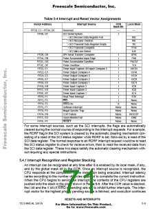
Table 5-4 Interrupt and Reset Vector Assignments
Vector Address
Interrupt Source
CCR
Mask Bit
Local Mask
FFC0, C1 – FFD4, D5
FFD6, D7
Reserved
—
I
—
SCI Serial System
• SCI Receive Data Register Full
• SCI Receiver Overrun
• SCI Transmit Data Register Empty
• SCI Transmit Complete
• SCI Idle Line Detect
SPI Serial Transfer Complete
Pulse Accumulator Input Edge
Pulse Accumulator Overflow
Timer Overflow
RIE
RIE
TIE
TCIE
ILIE
FFD8, D9
FFDA, DB
FFDC, DD
FFDE, DF
FFE0, E1
FFE2, E3
FFE4, E5
FFE6, E7
FFE8, E9
FFEA, EB
FFEC, ED
FFEE, EF
FFF0, F1
FFF2, F3
FFF4, F5
FFF6, F7
FFF8, F9
FFFA, FB
FFFC, FD
FFFE, FF
I
SPIE
PAII
I
I
PAOVI
TOI
I
Timer Input Capture 4/Output Compare 5
Timer Output Compare 4
Timer Output Compare 3
Timer Output Compare 2
Timer Output Compare 1
Timer Input Capture 3
Timer Input Capture 2
Timer Input Capture 1
Real-Time Interrupt
I
I4/O5I
OC4I
OC3I
OC2I
OC1I
IC3I
I
I
I
I
I
I
IC2I
I
IC1I
I
RTII
IRQ
I
None
None
None
None
NOCOP
CME
None
XIRQ Pin
X
Software Interrupt
None
None
None
None
None
Illegal Opcode Trap
COP Failure
Clock Monitor Fail
RESET
For some interrupt sources, such as the SCI interrupts, the flags are automatically
cleared during the normal course of responding to the interrupt requests. For example,
the RDRF flag in the SCI system is cleared by the automatic clearing mechanism con-
sisting of a read of the SCI status register while RDRF is set, followed by a read of the
SCI data register. The normal response to an RDRF interrupt request would be to read
the SCI status register to check for receive errors, then to read the received data from
the SCI data register. These two steps satisfy the automatic clearing mechanism with-
out requiring any special instructions.
5.4.1 Interrupt Recognition and Register Stacking
An interrupt can be recognized at any time after it is enabled by its local mask, if any,
and by the global mask bit in the CCR. Once an interrupt source is recognized, the
CPU responds at the completion of the instruction being executed. Interrupt latency
varies according to the number of cycles required to complete the current instruction.
When the CPU begins to service an interrupt, the contents of the CPU registers are
pushed onto the stack in the order shown in Table 5-5. After the CCR value is stacked,
the I bit and the X bit (if XIRQ is pending) are set to inhibit further interrupts. The inter-
rupt vector for the highest priority pending source is fetched, and execution continues
RESETS AND INTERRUPTS
TECHNICAL DATA
5-9
For More Information On This Product,
Go to: www.freescale.com

 FREESCALE [ Freescale ]