Freescale Semiconductor, Inc.
SMOD — Special Mode Select
Can be read any time. Can only be written in special modes (SMOD = 1). Can only be
written to zero. Refer to SECTION 4 OPERATING MODES AND ON-CHIP MEMORY
for more information.
MDA — Mode Select A
Can be read any time. Can only be written in special modes (SMOD = 1). Refer to
SECTION 4 OPERATING MODES AND ON-CHIP MEMORY for more information.
IRV — Internal Read Visibility
The IRV control bit allows internal read accesses to be available on the external data
bus during operation in expanded modes. In special modes (SMOD = 1), IRV resets
to one (enabled) and can be written any time. In normal modes (SMOD = 0), IRV re-
sets to zero (disabled) and only one write is allowed.
PSEL[3:0] — Priority Select Bits
These bits select one interrupt source to be elevated above all other I-bit-related
sources and can only be written while the I bit in the CCR is set (interrupts disabled).
Table 5-3 Highest Priority Interrupt Selection
PSEL3
PSEL2
PSEL1
PSEL0
Interrupt Source Promoted
Timer Overflow
0
0
0
0
0
0
0
0
1
1
1
1
1
1
1
1
0
0
0
0
1
1
1
1
0
0
0
0
1
1
1
1
0
0
1
1
0
0
1
1
0
0
1
1
0
0
1
1
0
1
0
1
0
1
0
1
0
1
0
1
0
1
0
1
Pulse Accumulator Overflow
Pulse Accumulator Input Edge
SPI Serial Transfer Complete
SCI Serial System
Reserved (Default to IRQ)
IRQ
Real-Time Interrupt
Timer Input Capture 1
Timer Input Capture 2
Timer Input Capture 3
Timer Output Compare 1
Timer Output Compare 2
Timer Output Compare 3
Timer Output Compare 4
Timer Output Compare 5/Input Capture 4
5.4 Interrupts
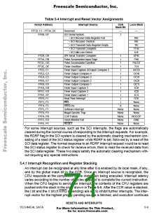
The MCU has 18 interrupt vectors that support 22 interrupt sources. The 15 maskable
interrupts are generated by on-chip peripheral systems. These interrupts are recog-
nized when the global interrupt mask bit (I) in the condition code register (CCR) is
clear. The three non-maskable interrupt sources are illegal opcode trap, software in-
terrupt, and XIRQ pin. Refer to Table 5-4, which shows the interrupt sources and vec-
tor assignments for each source.
RESETS AND INTERRUPTS
MC68HC11F1
5-8
TECHNICAL DATA
For More Information On This Product,
Go to: www.freescale.com

 FREESCALE [ Freescale ]