Freescale Semiconductor, Inc.
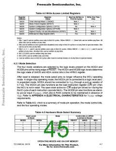
A normal mode is selected when MODB is logic one during reset. One of three reset
vectors is fetched from address $FFFA–$FFFF, and program execution begins from
the address indicated by this vector. If MODB is logic zero during reset, the special
mode reset vector is fetched from addresses $BFFA–$BFFF and software has access
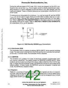
to special test features. Refer to SECTION 5 RESETS AND INTERRUPTS for infor-
mation regarding reset vectors.
4.3.1.1 HPRIO Register
Bits in the HPRIO register select the highest priority interrupt level, select whether
bootstrap ROM is present, and control visibility of internal reads by the CPU. After re-
set, MDA and SMOD select the operating mode.
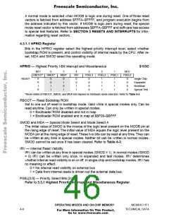
HPRIO — Highest Priority I-Bit Interrupt and Miscellaneous
$103C
Bit 7
6
5
4
IRV
0
3
2
1
Bit 0
RBOOT* SMOD*
MDA*
PSEL3
PSEL2
PSEL1
PSEL0
RESET:
0
0
1
0
0
0
1
1
0
1
0
1
0
0
0
0
1
1
1
1
1
1
1
1
0
0
0
0
Single Chip
Expanded
Bootstrap
0
1
1
Special Test
*Reset states of RBOOT, SMOD, and MDA bits depend on hardware mode selection. Refer to Table 4-3.
RBOOT — Read Bootstrap ROM
Set to one out of reset in bootstrap mode. Valid while in special modes only. Can be
read anytime. Can only be written in special modes.
0 = Bootloader ROM disabled and not in map
1 = Bootloader ROM enabled and in map at $BF00–$BFFF
SMOD and MDA — Special Mode Select and Mode Select A
The initial value of SMOD is the inverse of the logic level present on the MODB pin at
the rising edge of reset. The initial value of MDA equals the logic level present on the
MODA pin at the rising edge of reset.These two bits can be read at any time.They can
be written at any time in special modes. Neither bit can be written is normal modes.
SMOD cannot be set once it has been cleared. Refer to Table 4-3.
IRV — Internal Read Visibility
IRV can be written at any time in special modes (SMOD = 1). In normal modes (SMOD
= 0) IRV can be written only once. In expanded and test modes, IRV determines
whether internal read visibility is on or off. In single-chip and bootstrap modes, IRV has
no meaning or effect.
0 = No internal read visibility on external bus
1 = Data from internal reads is driven out the external data bus.
PSEL[3:0] — Priority Select Bits [3:0]
Refer to 5.3.1 Highest Priority Interrupt and Miscellaneous Register.
OPERATING MODES AND ON-CHIP MEMORY
MC68HC11F1
4-8
TECHNICAL DATA
For More Information On This Product,
Go to: www.freescale.com

 FREESCALE [ Freescale ]