Freescale Semiconductor, Inc.
10.7 Operation in STOP and WAIT Modes
If a conversion sequence is in progress when either the STOP or WAIT mode is en-
tered, the conversion of the current channel is suspended. When the MCU resumes
normal operation, that channel is resampled and the conversion sequence is resumed.
As the MCU exits the WAIT mode, the A/D circuits are stable and valid results can be
obtained on the first conversion. However, in STOP mode, all analog bias currents are
disabled and it is necessary to allow a stabilization period when leaving the STOP
mode. If the STOP mode is exited with a delay (DLY = 1), there is enough time for
these circuits to stabilize before the first conversion. If the STOP mode is exited with
no delay (DLY bit in OPTION register = 0), allow 10 ms for the A/D circuitry to stabilize
to avoid invalid results.
10.8 A/D Control/Status Registers
All bits in this register can be read or written, except CCF (bit 7), which is a read-only
status indicator, and bit 6, which always reads as zero. Write to ADCTL to initiate a
conversion. To quit a conversion in progress, write to this register and a new conver-
sion sequence begins immediately.
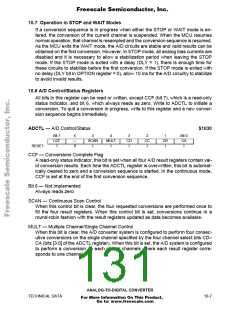
ADCTL — A/D Control/Status
$1030
Bit 7
CCF
1
6
—
0
5
SCAN
I
4
MULT
I
3
CD
I
2
CC
I
1
CB
I
Bit 0
CA
I
RESET:
CCF — Conversions Complete Flag
A read-only status indicator, this bit is set when all four A/D result registers contain val-
id conversion results. Each time the ADCTL register is overwritten, this bit is automat-
ically cleared to zero and a conversion sequence is started. In the continuous mode,
CCF is set at the end of the first conversion sequence.
Bit 6 — Not implemented
Always reads zero
SCAN — Continuous Scan Control
When this control bit is clear, the four requested conversions are performed once to
fill the four result registers. When this control bit is set, conversions continue in a
round-robin fashion with the result registers updated as data becomes available.
MULT — Multiple Channel/Single Channel Control
When this bit is clear, the A/D converter system is configured to perform four consec-
utive conversions on the single channel specified by the four channel select bits CD–
CA (bits [3:0] of the ADCTL register). When this bit is set, the A/D system is configured
to perform a conversion on each of four channels where each result register corre-
sponds to one channel.
ANALOG-TO-DIGITAL CONVERTER
TECHNICAL DATA
10-7
For More Information On This Product,
Go to: www.freescale.com

 FREESCALE [ Freescale ]