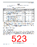
Electrical Characteristics
A.8
Electrical Specification for Voltage Regulator
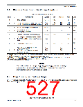
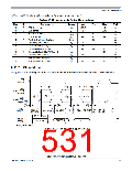
Table A-24. IVREG Characteristics
Num
C
Characteristic
Symbol
Min
Typical
Max
Unit
VVDDR,A
1
2
P
Input Voltages
3.13
—
5.5
V
VDDA Low Voltage Interrupt Assert Level (1)
VDDA Low Voltage Interrupt Deassert Level
VLVIA
VLVID
4.04
4.19
4.23
4.38
4.40
4.49
V
V
P
VDDX Low Voltage Reset Deassert (2) (3)
VLVRXD
fACLK
3
4
5
P
T
—
—
—
10
—
3.13
—
V
KHz
—
API ACLK frequency
(APITR[5:0] = %000000)
Trimmed API internal clock(4) ∆f / fnominal
dfACLK
C
- 5%
+ 5%
The first period after enabling the counter
by APIFE might be reduced by API start up
delay
tsdel
6
7
D
T
—
—
100
6.5
us
mV/
oC
dVTS
Temperature Sensor Slope
4.0
5.5
High Temperature Interrupt Assert
(CPMUHTTR=$88)(5)
High Temperature Interrupt Deassert
(CPMUHTTR=$88)
THTIA
THTID
125
105
oC
8
T
1. Monitors VDDA, active only in Full Performance Mode. Indicates I/O & ADC performance degradation due to low supply
voltage.
2. Device functionality is guaranteed on power down to the LVR assert level
3. Monitors VDDX, active only in Full Performance Mode. MCU is monitored by the POR in RPM (see Figure A-4)
4. The API Trimming APITR[5:0] bits must be set so that fACLK=10KHz.
5. A hysteresis is guaranteed by design
NOTE
The LVR monitors the voltages V , V
and V
. As soon as voltage
DDX
DD
DDF
drops on these supplies which would prohibit the correct function of the
microcontroller, the LVR is triggering a reset.
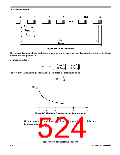
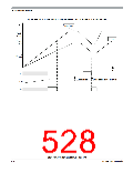
A.9
Chip Power-up and Voltage Drops
LVI (low voltage interrupt), POR (power-on reset) and LVRs (low voltage reset) handle chip power-up or
drops of the supply voltage.
S12P-Family Reference Manual, Rev. 1.13
Freescale Semiconductor
527

 FREESCALE [ Freescale ]