Electrical Characteristics
A.6
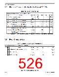
Electrical Characteristics for the Oscillator (OSCLCP)
Table A-22. OSCLCP Characteristics
Conditions are shown in Table A-4 unless otherwise noted
Num C
Rating
Symbol
fOSC
Min
4.0
100
—
Typ
Max
Unit
MHz
µA
1
2
C Crystal oscillator range
16
iOSC
P Startup Current
Oscillator start-up time (LCP, 4MHz)(1)
C
tUPOSC
tUPOSC
tUPOSC
fCMFA
3a
3b
3c
4
2
1.6
1
10
8
ms
Oscillator start-up time (LCP, 8MHz)1
C
—
—
ms
Oscillator start-up time (LCP, 16MHz)1
C
5
ms
P Clock Monitor Failure Assert Frequency
D Input Capacitance (EXTAL, XTAL pins)
C EXTAL Pin Input Hysteresis
200
400
7
1000
KHz
pF
CIN
5
VHYS,EXTAL
—
—
—
—
6
180
mV
EXTAL Pin oscillation amplitude (loop
VPP,EXTAL
7
C
0.9
V
controlled Pierce)
1. These values apply for carefully designed PCB layouts with capacitors that match the crystal/resonator requirements.
A.7
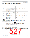
Reset Characteristics
Table A-23. Reset and Stop & Startup Characteristics
Conditions are shown in Table A-4 unless otherwise noted
Num
C
Rating
Symbol
Min
Typ
Max
Unit
1
C Reset input pulse width, minimum input time
PWRSTL
2
tVCORS
T
2
3
C Startup from Reset
nRST
768
50
tVCORS
T
C STOP recovery time
tSTP_REC
µs
S12P-Family Reference Manual, Rev. 1.13
526
Freescale Semiconductor

 FREESCALE [ Freescale ]