Serial Communications Interface Module (SCI)
START BIT
LSB
PTF4/RxD
START BIT
QUALIFICATION
START BIT
VERIFICATION
DATA
SAMPLING
SAMPLES
RT
CLOCK
RT CLOCK
STATE
RT CLOCK
RESET
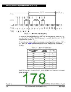
Figure 13-7. Receiver Data Sampling
To locate the start bit, data recovery logic does an asynchronous search for a 0
preceded by three 1s. When the falling edge of a possible start bit occurs, the RT
clock begins to count to 16.
To verify the start bit and to detect noise, data recovery logic takes samples at RT3,
RT5, and RT7. Table 13-1 summarizes the results of the start bit verification
samples.
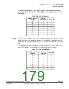
Table 13-1. Start Bit Verification
RT3, RT5, and RT7
Samples
Start Bit
Verification
Noise Flag
000
001
010
011
100
101
110
111
Yes
Yes
Yes
No
0
1
1
0
1
0
0
0
Yes
No
No
No
If start bit verification is not successful, the RT clock is reset and a new search for
a start bit begins.
Data Sheet
178
MC68HC908MR32 • MC68HC908MR16 — Rev. 6.0
Serial Communications Interface Module (SCI)
MOTOROLA

 FREESCALE [ Freescale ]