Serial Communications Interface Module (SCI)
13.3.2.6 Transmitter Interrupts
These conditions can generate CPU interrupt requests from the SCI transmitter:
•
SCI transmitter empty (SCTE) — The SCTE bit in SCS1 indicates that the
SCDR has transferred a character to the transmit shift register. SCTE can
generate a transmitter CPU interrupt request. Setting the SCI transmit
interrupt enable bit, SCTIE, in SCC2 enables the SCTE bit to generate
transmitter CPU interrupt requests.
•
Transmission complete (TC) — The TC bit in SCS1 indicates that the
transmit shift register and the SCDR are empty and that no break or idle
character has been generated. The transmission complete interrupt enable
bit, TCIE, in SCC2 enables the TC bit to generate transmitter CPU interrupt
requests.
13.3.3 Receiver
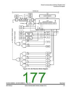
Figure 13-6 shows the structure of the SCI receiver.
13.3.3.1 Character Length
The receiver can accommodate either 8-bit or 9-bit data. The state of the M bit in
SCI control register 1 (SCC1) determines character length. When receiving 9-bit
data, bit R8 in SCI control register 2 (SCC2) is the ninth bit (bit 8). When receiving
8-bit data, bit R8 is a copy of the eighth bit (bit 7).
13.3.3.2 Character Reception
During an SCI reception, the receive shift register shifts characters in from the
PTF4/RxD pin. The SCI data register (SCDR) is the read-only buffer between the
internal data bus and the receive shift register.
After a complete character shifts into the receive shift register, the data portion of
the character transfers to the SCDR. The SCI receiver full bit, SCRF, in SCI status
register 1 (SCS1) becomes set, indicating that the received byte can be read. If the
SCI receive interrupt enable bit, SCRIE, in SCC2 is also set, the SCRF bit
generates a receiver CPU interrupt request.
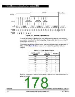
13.3.3.3 Data Sampling
The receiver samples the PTF4/RxD pin at the RT clock rate. The RT clock is an
internal signal with a frequency 16 times the baud rate. To adjust for baud rate
mismatch, the RT clock is resynchronized at these times (see Figure 13-7):
•
•
After every start bit
After the receiver detects a data bit change from 1 to 0 (after the majority of
data bit samples at RT8, RT9, and RT10 return a valid 1 and the majority of
the next RT8, RT9, and RT10 samples return a valid 0)
Data Sheet
176
MC68HC908MR32 • MC68HC908MR16 — Rev. 6.0
Serial Communications Interface Module (SCI)
MOTOROLA

 FREESCALE [ Freescale ]