Freescale Semiconductor, Inc.
Serial Communications Interface (SCI)
17.5.1 Data Format
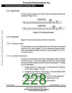
The SCI uses the standard non-return-to-zero mark/space data format
illustrated in Figure 17-3.
8-BIT DATA FORMAT
PARITY
(BIT M IN SCC1 CLEAR)
OR DATA
NEXT
START
BIT
BIT
START
BIT
STOP
BIT
BIT 0 BIT 1
BIT 0 BIT 1
BIT 2 BIT 3 BIT 4 BIT 5 BIT 6 BIT 7
9-BIT DATA FORMAT
(BIT M IN SCC1 SET)
PARITY
OR DATA
BIT
NEXT
START
BIT
START
BIT
BIT 2 BIT 3 BIT 4 BIT 5 BIT 6 BIT 7 BIT 8 STOP
BIT
Figure 17-3. SCI Data Formats
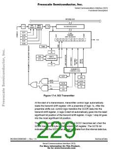
17.5.2 Transmitter
Figure 17-4 shows the structure of the SCI transmitter.
17.5.2.1 Character Length
The transmitter can accommodate either 8-bit or 9-bit data. The state of
the M bit in SCI control register 1 (SCC1) determines character length.
When transmitting 9-bit data, bit T8 in SCI control register 3 (SCC3) is
the ninth bit (bit 8).
17.5.2.2 Character Transmission
During an SCI transmission, the transmit shift register shifts a character
out to the TxD pin. The SCI data register (SCDR) is the write-only buffer
between the internal data bus and the transmit shift register. To initiate
an SCI transmission:
1. Enable the SCI by writing a logic 1 to the enable SCI bit (ENSCI)
in SCI control register 1 (SCC1).
2. Enable the transmitter by writing a logic 1 to the transmitter enable
bit (TE) in SCI control register 2 (SCC2).
3. Clear the SCI transmitter empty bit (SCTE) by first reading SCI
status register 1 (SCS1) and then writing to the SCDR.
4. Repeat step 3 for each subsequent transmission.
Technical Data
MC68HC908AS60 — Rev. 1.0
Serial Communications Interface (SCI)
For More Information On This Product,
Go to: www.freescale.com

 FREESCALE [ Freescale ]