FUNCTIONAL DEVICE OPERATION
OPERATIONAL MODES
Bank 1
IC 3 “Child”
GO
Bank 2
IC 1 “Parent”
GO
IC 2 “Parent”
GO
GO
GO
GO
GIN
GIN
GIN
GIN
GIN
0
1
2
3
0
1
2
3
0
GIN
0
0
0
1
2
3
IGBT1
4
IGBT1
Gate Drive 0
(0-3)
IGBT2
Gate Drive 0
GO
6
GO
GO
GO
GIN
1
GIN
1
1
IGBT1
5
Gate Drive 1
Gate Drive 1
GO
IGBT 2
(0-3)
2
GIN
GIN
2
2
Gate Drive 2
Gate Drive 2
GO
3
GIN
3
GIN
3
IGBT2
Gate Drive 3
4
7
Gate Drive 3
4 GIN
(0-3)
4
GIN (0-3)
NOMI
GIN (0-3)
LOGIC
LOGIC
NOMI
LOGIC
MAXI
NOMI
MAXI
MAXI
NOMI
RSP1
RSP
RSP2
VtNI
VtNI
NOMI
Comparator
Child
VtNI
NOMI
disabled
Ign 1
Comparator
Inputs Tied
to GND
Ign 2
RS1
RS2
Comparator
VtMI
MAXI
VtMI
MAXI
disabled
VtMI
MAXI
Logic
Buffer
Logic
Buffer
Comparator
Comparator
Logic
Buffer
Logic
Buffer
Logic
Buffer
Logic
Buffer
MAXI
NOMI
NOMI
MAXI
MAXI
NOMI
NOMI1 to uP
MAXI1 to uP
MAXI2 to uP
NOMI2 to uP
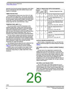
Note: For “child” input NOMI is for channel 1&3, input MAXI is for channel 0&2
Figure 10. V10 Mode
LOW SIDE INJECTOR DRIVER
ON/OFF CONTROL COMMAND
The four open drain low side injector drivers are designed
to control various automotive loads such as injectors,
solenoids, lamps, relays and unipolar stepper motors. Each
driver includes off and on state open load detection, short
circuit protection and diagnostics. The injector drivers are
individually controlled through the ON/OFF SPI input
command Table 20 or parallel input pins DIN0 to DIN3. Serial
and parallel control of the output state is determined by the
logical OR of the SPI serial bit and the DINx parallel input
pins. All four outputs are disabled when the OUTEN input pin
is high regardless of the state of the SPI control bit or the
state of the DINx pin. All four injector drivers are not affected
by the selection of the gate driver’s three modes of operation
(Ignition Mode, General Purpose Mode, V10 mode).
To program the individual output of the 33810 ON or OFF,
a 16-bit serial stream of data is entered into the SI pin. The
first 4 bits of the control word are used to identify the On/Off
Command. Bit 0 through bit 3 of the ON/OFF Control
Command turn ON or OFF the specific output driver.
INJECTOR DRIVER FAULT COMMANDS
Fault protection strategies for the injector drivers are
programmed by the SPI LSD Fault Command. Bit 8 through
11 determine the type of short circuit protection to be used,
bits 0 through 7 set the open load strategy.
Short-circuit protection consists of three strategies. All
strategies utilize current limiting as an active element to
protect the output driver from failure.The TLIM and Timer
options are used to enhance the short circuit protection
strategy of the Injector drivers. The timer protection scheme
uses a low duty cycle in the event of a short-circuit. The T
LIM
33810
Analog Integrated Circuit Device Data
Freescale Semiconductor
25

 FREESCALE [ Freescale ]