FUNCTIONAL DEVICE OPERATION
OPERATIONAL MODES
Each gate driver is individually set to either, restore to the
pre-fault state, or shutdown when a short fault is declared. By
setting the Retry/Shutdown bit in the GPGD Fault Operation
Command to logic 1 the specific output will try to go back to
the pre-fault state when the fault is no longer declared, after
a programmed “inhibit time”.
Table 14. FBx Fault Threshold Select
GPGD VDS FLT
FBx Fault Threshold Select
Bits
000
001
010
011
100
101
110
111
0.5V
1.0V
The retry strategy will cause the output to try to return to
the pre-fault state on a 1% duty cycle basis. For example: If
the fault timer is set to 120µs and a fault is declared (drain
voltage greater than the programmed threshold for greater
than 120µs), the GDx output driver will be forced off for 12ms.
After 12 ms has elapsed, if the inputs, GINx or SPI, have not
tried to shut off the particular GDx output in the interim, the
GDx output will try to set the external driver on again (the pre-
fault state). A continued declared fault on the output would
result in another 12ms shutdown period.
1.5V
2.0 (default)
2.5V
3.0V
No Change
No Change
By setting the Retry/Shutdown bit in the GPGD Fault
Operation Command to logic 0 the specific output will
shutdown and remain off when the short fault is declared.
Only a reissue of the turn on command, via SPI or GINx, will
force the output to try and turn on again.
GPGD SHORT TIMER COMMAND
The GPGD Short Timer Command allows the user to
select the duration of time that the drain voltage is allowed to
be greater than the programed threshold voltage without
causing shutdown. External MOSFETS with drain voltages
greater than the programed threshold for longer than the
Fault Duration Timer are shutdown. Timer durations are listed
in Table 15.
In the event that a GPGD is selected as a PWM controller
and a short occurs on the output, the output retry strategy
forces the output to a 1% duty cycle based on the fault timer
setting. For example: If the fault timer is set to 120µs and a
fault is detected (drain voltage greater than programmed
threshold), the PWM output will be commanded off for 12ms
and commanded ON again at the next PWM cycle.
Care should be taken to select a fault timer that is shorter
than the minimum duty cycle ON time of the PWM controller.
Selecting a fault timer that is longer will allow the PWM
controller to continue to drive the external MOSFET into a
shorted load.
Table 15. FBx Short Fault Timer
GPGD FLT Timer
Fault Timer Select
Bits
000
001
010
011
100
101
110
111
30µs
60µs
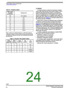
PWM FREQUENCY/DUTY CYCLE COMMAND
The PWMx Freq & Duty Cycle command is use to program
the GDx outputs with a frequency and duty cycle. Table 16
defines the user selectable output frequency. The frequency
and duty cycle may be updated at any time using the PWM
Freq&DC command, however the update will only begin on
the next PWM rising edge time.
120µs
240µs (default)
480µs
960µs
Once the PWM Freq & DC registers are programmed and
the PWM controller is enabled through the Mode Command
the PWM outputs are turned ON and OFF via the GINx pin
OR the SPI GPGD ON/OFF Command control bit. All Parallel
and serial On and Off command updates to the PWM
controller are synchronous with the rising edge of the
previous PWM period.
No Change
No Change
Notes: Tolerance on this fault timer setting is ±10% after using the
Calibration Command.
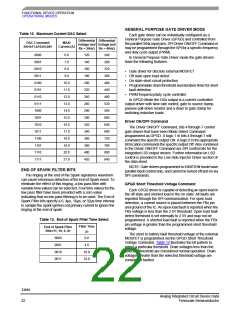
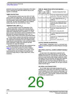
GPGD FAULT OPERATION COMMAND
The truth table for GDx control in general purpose mode is
provided in Table 8.
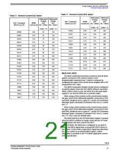
The GPGD Fault Operation Command sets the operating
parameters for the gate drivers under faulted conditions. A
short fault is said to be “detected” when the drain source
voltage, Vds, of the external MOSFET, exceeds the SPI
programmed short threshold voltage. The short fault is said
to be “declared” when the VDS over-voltage lasts longer than
the SPI programmed “fault timer.” (short duration time > fault
timer programmed value)
The duty cycle of the PWM outputs is controlled by bits 0-
6, inclusive. The duty cycle value is 1% per binary count from
1-100 with counts of 101-127 defaulting to 100%. For
example, sending SPI command 101001000001100 would
set GD1, PWM output to 10Hz and 12% duty cycle.
33810
Analog Integrated Circuit Device Data
Freescale Semiconductor
23

 FREESCALE [ Freescale ]