FUNCTIONAL DEVICE OPERATION
OPERATIONAL MODES
protection circuit uses the junction temperature of the output
driver to determine the fault. Both methods may be used
together or individually.
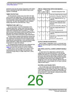
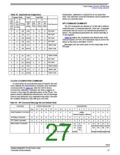
Table 18. Injector Driver (OUTx) Fault Operation
Shutdn
Retry
Fault
Timer
Bit 9
TLIM
Operation During Short Fault
Bit 11 Bit 10
TIMER PROTECTION
Timer only, Outputs will retry on period
1
0
X
The first protection scheme uses a low ON to OFF duty
cycle to protect the output driver. The low duty cycle allows
the device to cool so that the maximum junction temperatures
are not exceeded. During a short condition, the device enters
current limit. The driver will shutdown for short conditions
lasting longer than the current limit timer (~60µs)
OUT0-OUT3 = 60 µs ON, ~10ms OFF
T
only, Outputs will retry on T
LIM
1
1
1
1
0
1
LIM
hysteresis.
Timer and T , Outputs will retry on
LIM
period and driver temperature below
threshold.
TEMPERATURE LIMIT (TLIM
)
OUT0-OUT3= 60 µs ON, ~10ms OFF
The second scheme senses the temperature of the
individual output driver. During a short event the device
enters current limit and will remain in current limit until the
output driver temperature limit is exceeded (TLIM). At this
point, the device will shutdown until the junction temperature
Timer only, Outputs will not retry on
period
0
0
X
OUT0-OUT3 = 60 µs ON, OFF
T
only, Outputs will not retry on TLim
0
0
1
1
0
1
LIM
falls below the hysteresis temperature value. The T
hysteresis.
LIM
hysteresis value is listed in the previous specification tables.
Timer and T , Outputs will not retry on
LIM
The third method combines both protection schemes into
one. During a short event the device will enter current limit.
The output driver will shutdown for short conditions lasting
longer than the current limit timer. In the event that the output
driver temperature is higher than maximum specified
temperature the output will shutdown.
period or T
.
LIM
OUT0-OUT3 = 60 µs ON, OFF
OUTPUT DRIVER DIAGNOSTICS.
Short to battery, Temperature Limit (TLIM) and open load
faults are reported through the All Status Response message
Table 21.
The Shutdown/Retry bit allows the user to determine how
the drivers will respond to each short circuit strategy.
Table 18 provides fault operation for all three strategies.
Outputs may be used in parallel to drive higher current
loads provided the turn-off energy of the load does not
exceed the energy rating of a single output driver (100mJ
maximum).
OFF OPEN LOAD PULL-DOWN CURRENT ENABLE
BITS
An open load on the output driver is detected by the
voltage level on the drain of the MOSFET in the off state.
Internal to the device is a 75µA pull-down current sink. In the
event of an open load the drain voltage is pulled low. When
the voltage crosses the threshold, and open load is detected.
The pull-down current source may be disabled by bit 0
through bit 3 in the LSD Fault Command. With the driver off
and the Off Open Load bit disabled, the Off Open Load fault
status bit will be logic 0.
ON OPEN LOAD ENABLE BITS
The On State Open Load enable bit allows the user to
determine an On State Open Load. When the On State Open
Load bit disabled, the On State Fault bit is always logic 0. On
Open Load is determined by monitoring the current through
the OUTx MOSFET. In the ON state, currents less than 20mA
to 200mA are considered open.
33810
Analog Integrated Circuit Device Data
Freescale Semiconductor
26

 FREESCALE [ Freescale ]